EdgeTX User Manual
v2.11
v2.11
  • EdgeTX User Manual v2.11
  • Summary of changes since v2.10
  • Installing and Updating EdgeTX
    • Migrate from OpenTX to EdgeTX using EdgeTX Buddy
    • Migrate from OpenTX to EdgeTX using the Bootloader
    • Update from an earlier version of EdgeTX using EdgeTX Buddy
    • Update from an earlier version of EdgeTX using the Bootloader
    • Having trouble updating?
  • User Manual for Color Screen Radios
    • User Interface
      • Virtual Keyboards
      • Trim Navigation
    • Manage Models
    • Channel Monitor
    • Model Settings
      • Model Setup
        • Internal / External RF
        • Trainer
        • Timer 1/2/3
        • Pre-start Checks
        • Trims
        • Throttle
        • Enabled Features
        • USB Joystick
        • Customizable Switches
        • Other
      • Heli Setup
      • Flight Modes
      • Inputs, Mixes & Outputs
        • Inputs
        • Mixes
        • Outputs
      • Curves
      • Global Variables
      • Logical Switches
      • Special Functions
      • Custom Scripts
      • Telemetry
        • Sensor Configuration Options
        • Common Telemetry Sensors
    • Radio Settings
      • Tools
      • SD Card
      • Radio Setup
        • Additional Radio settings
      • Themes
      • Global Functions
      • Trainer
      • Hardware
      • Version
    • Screen Settings
      • Widgets
    • Reset Telemetry
    • Statistics
  • User Manual for Monochrome Screen Radios
    • User Inteface
    • Main View
      • Reset
      • Statistics
    • Model Settings
      • Setup
      • Heli Setup
      • Flight / Drive Modes
      • Inputs, Mixes & Outputs
        • Inputs
        • Mixes
        • Outputs
      • Curves
      • Logical Switches
      • Special Functions
      • Telemetry
        • Sensor Configuration
        • Common Telemetry Sensors
      • Display
    • Radio Settings
      • SD Card
      • Radio Setup
      • Global Functions
      • Trainer
      • Hardware
      • Version
  • Translated User Manuals
  • EdgeTX: How-To
    • Access DFU and Bootloader Mode
    • Contribute to the User Manual
    • Set-up wireless trainer with a Multi -protocol module
    • Use Bluetooth with EdgeTX
    • Configure Advanced Joystick with EdgeTX
    • Joystick Mapping Information for Game Developers
    • Disable Touchscreen
    • Use Trims to Adjust Global Variables
    • Configure a low battery alert
  • More
    • Additional Resources
    • Contributors
Powered by GitBook
On this page
Export as PDF
  1. User Manual for Color Screen Radios
  2. Model Settings
  3. Model Setup

Customizable Switches

PreviousUSB JoystickNextOther

Last updated 18 days ago

A traditional 6 position switch/control is either a group of 6 switches that work together (where only one can be active at one time) or a single rotary switch that has six physical positions (detents). Some newer generation radios provide the "Customizable Switch" capability, which allows you to define type, grouping and startup state of the switches. Physically, they look like a regular 6 position switch which you will see on older handset designs, but they are much, much, more flexible.

If you do need the customizable switches to behave exactly like the traditional 6POS switch, you need to configure six customisable switches to be in a single group, set that group to be "Always On", and Startup for the group set to the first switch. You will then be able to use, for example, GR1 in place of 6POS.
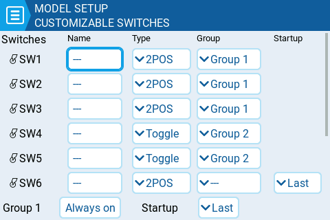
Name: Whichever three letter name you wish to give each customisable switch.

Type: Can be set to any of the following

  • None : basically disabled

  • Toggle : customizable switch is only "active" while being pushed

  • 2POS : pushing the switch will alternate it's state. i.e. OFF push ON push OFF ....

Group: This is where you choose how the individual switches should be grouped. You can choose for them to be in a single group (the default, Group 1), and then they can be used like a traditional 6POS switch. Or, you can define them to be in seperate groups (e.g. as shown for SW1-SW3 and SW4-SW5 above), or even for some switches to not be in a group at all (e.g. SW6 as shown above). You can use the various groups as a source for inputs or mixes via the GR# option, where the # represents the number of the group (e.g. GR1, GR2).

When switches are grouped, only one switch in the group can be active at a time. Additionally, you can specify that one switch in the group must always be on "Always on".

Startup: Here is where you specify the startup state for either a 2POS customizable switch not in a group, or for a group of customizable switches. You can specify it to be "Last" (remember the last state when the transmitter was powered off or model changed) or in the up (released) or down (pressed) state.

OFF / ON Colors (on compatible handsets): Some handsets support configuring the color of the customizable switches. If so, the OFF and ON color pickers will be shown for each customisable switch (as shown below) and you will be able to pick your preferred colour for each state. Black represents when the customizable switch is not illuminated.
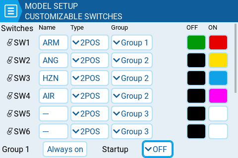
Example of Customizable Switch options on one supported handset.
Customizable Switch options on a handset that also supports configuring the LED colors