
Loading...
Loading...
Loading...
Loading...
Loading...
Loading...
Loading...
Loading...
Loading...
Loading...
Loading...
Loading...
Loading...
Loading...
Loading...
Loading...
Loading...
Loading...
Loading...
Loading...
Loading...
Loading...
Loading...
Loading...
Loading...
Loading...
Loading...
Loading...
Loading...
Loading...
Loading...
Loading...
Loading...
Loading...
Loading...
Loading...
Loading...
Loading...
Loading...
Loading...
Loading...
Loading...
Loading...
Loading...
Loading...
Loading...
Loading...
Loading...
Loading...
Loading...
Loading...
Loading...
Loading...
Loading...
Loading...
Loading...
Loading...
Loading...
Loading...
Loading...
Loading...
Loading...
Loading...
Loading...
Loading...
Loading...
Loading...
Loading...
Loading...
Loading...
Loading...
Loading...
Loading...
Loading...
Loading...
Loading...
Loading...
Loading...
Loading...
Loading...
Loading...
Loading...
Loading...
Loading...
Loading...
Loading...
Loading...
Loading...
Loading...
Loading...
Loading...
Loading...
Loading...
Loading...
If you would like to contribute to this guide, please take a look at the Contribute to the User Manual page.
The purpose of this user manual is to consolidate information from the community about the setup, configuration, and use of EdgeTX. The goal is to be your "one-stop shop" for information about anything related to EdgeTX. It is broken down into the following areas:
The user guide explains all the configuration options available in EdgeTX as well as some high-level theoretical information about EdgeTX usage and model controls. It is broken into sections - one section covering the interface for Color Screen Radiosand one section covering the interface for
The How-to section will provide detailed instructions about how to configure model or user-specific use cases in EdgeTX. It will cover common use cases as well as rare and specific use cases. This section of the manual will steadily grow as new How-to articles are submitted by contributors.
This section of the knowledge base will contain links to additional resources that EdgeTX users may find useful. The external pages that are linked here are not maintained by EdgeTX. However, they are listed as they may be useful sources of additional information relating to EdgeTX.
See the section for a list of direct and indirect contributors.
Whenever a new model is loaded, EdgeTX will conduct pre-flight checks based on the checks that are configured on this page. If any of the checks are failed, EdgeTX will give the user an audio and visual warning that must be acknowledged before using the model. The following preflight checks are configurable:
Display checklist - When this option is selected, the model notes file will be displayed when the model is loaded. A valid model notes file must be in the Models folder on the SD card. The model notes file must be a .txt file and must have the EXACT same name as the model it is for, for example: Mobula6.txt. The text in the file is up to the user.
Interactive checklist - This option is used with the Display checklist option. When this option is selected, any line of text in the checklist file that begins with = will display as a check box when the checklist is displayed. All displayed checkboxes must be checked by selecting them in order to close the checklist.
Throttle state - When selected, the radio will check that the throttle is at the minimum range value for the configured throttle source in the menu.
There are several ways to install or update EdgeTX on your radio transmitter. You can use the online tool EdgeTX buddy or manually install/update the bootloader and firmware using the bootloader method. There are advantages and disadvantages to both ways, so really, it boils down to person preference.
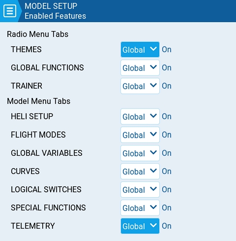
The Enabled Features section of Model Setup allows you to configure which tabs are visible in the selected model's radio setup and model settings area of EdgeTX. You can select the following options:
Global - When selected, the tab will take the global value configured in the Enabled Features area in Radio Setup. The configured global value will display next to the option.
On - When selected, this tab will be visible when this model is loaded.
Firmware and SD card contents are all located in one location
It takes you step by step through the process
Normally a simple process.
Must use a Chromium-based browser to access (Chrome, MS Edge, Brave, Opera, etc.)
You must have the correct STM32 drivers installed on your computer. Usually, this is automatic. However, some computers install incorrect drivers, which can make this process more difficult.
Flashing always works
The flashing process is quicker.
Does not rely on your computer for flashing
Firmware, SD Card, and Sound files must be downloaded individually from different locations and placed manually on the SD Card.
Whichever way you choose, there is a guide that will help you. Below are the migration guides and installation guides for both methods:
Switches - The section displays all the switches that are configured on the radio and allows you to select which position is the correct position for the switch state check. Selecting the switch will cycle through the available switch positions or turn the check off for the switch completely. Yellow switches have the switch position check activated. White switches are de-activated. A long press (or touch) of [Enter] while this section is highlighted will set all the switch positions to the currently configured physical positions of the switches.
Pots & Sliders- When activated, this option checks the position of the pots & sliders. There are three options - OFF, ON and AUTO. When ON or AUTO is selected from the drop-down menu, buttons for the available pots and sliders will appear.
OFF - Pot and slider positions are not checked.
ON - Positions are checked against manually configured pot and slider positions that are set to active (yellow). To manually set the check position, select ON from the drop-down menu, put the pots and sliders into the desired position, and activate them by selecting them (yellow).
AUTO - Positions are checked for activated pots and sliders and compared to the last automatically saved position before the radio was turned off or the model was changed.
Off - When selected, this tab will not be visible when this model is loaded.
In order to update from OpenTX to EdgeTX you will need to have both OpenTX & EdgeTX Companion installed on your computer. You can download OpenTX Companion from: https://downloads.open-tx.org/2.3/release/companion/. You can download EdgeTX Companion from: https://github.com/EdgeTX/edgetx/releases (File name: edgetx-cpn-[operation system]-[version].zip)
Turn on your radio, navigate to Radio Settings, Hardware and scroll down to the bottom of the screen and select EEPROM backup. If you do not have this option, then your radio does not store your data in EEPROM and this step can be skipped.
With your radio powered on, plug your radio into your computer via USB. When prompted by your radio for the USB mode, select USB Storage.
With your computer, copy the entire contents of your SD card to a safe place on your Computer. If you ever decide to go back to OpenTX you can use these files again. If you backed up your EEPROM in the step above, check the EEPROM folder to make sure that there is a recent backup file in there.
Start OpenTX Companion.
Select the Backup radio to file icon from the left side of the screen as shown below. Select a saving location (desktop is fine) and give it a descriptive name.
After the file has been saved, close OpenTX Companion. Unplug the radio from the computer and power it off.
Download and extract the EdgeTX SD card content for your radio type to your computer. The SD card contents can be found here:
The list below shows which .zip file to use for different radio types:
c480x272.zip (480x272 Horizontal Color Screen) - TX16s, T16, Horus x10s,Horus x12s, most color screen radios...
c480x320.zip (480x320 Horizontal Color Screen)
c320x480.zip (320x480 Verticle Color Screen)- FlySky Nirvana NV14, EL18
bw128x64.zip (128x64 BW Screens) -All monochrome screen radios
Delete everything from your SD card and copy the contents of the unzipped folder to your blank SD card. (If you did a format, ensure it is set to fat32)
Copy over any custom sounds, model images, widgets or Lua scripts to their respective folders.
Download the desired sound pack (if you didn’t transfer your existing sounds) (), unzip and copy to the "Sounds" folder on your SD card.
Download the current EdgeTX firmware. You can download the latest release .zip file (edgetx-firmware-vX.X.X.zip) directly from Github -
Unzip the file and save the correct .bin file (same name as your radio type) to the "Firmware" folder on the SD card for your radio.
Turn on your radio and navigate to the SD card screen. Open the "Firmware" folder and select the EdgeTX firmware file that you just copied to your SD card. Once the file is selected, select the option to "Flash bootloader". The bootloader will be flashed to the EdgeTX bootloader.
Exit back to the main screen and then shut off your radio.
Boot your radio in bootloader mode by holding trim switches T4 and T1 to center while pushing the power button on.
You should now see the EdgeTX bootloader. Select the option "Write Firmware". Select the EdgeTX firmware file that you saved to your SD card. Long-press to flash it.
After the flashing is complete, select "Exit". The radio will restart and you should be greeted with "Welcome EdgeTX".
When the radio starts with EdgeTX for the first time, you will get a warning: STORAGE WARNING - Missing or Bad Radio Data-. Press the white circle or roller to bypass the warning. Then you will get another STORAGE WARNING - Storage Preparation. Press the white circle or roller again. Once the SD card is prepared, the calibration screen will appear. Calibrate your radio.
At this point, you now have the EdgeTX Bootloader, Firmware and the SD card contents installed. The last step is to convert your models over from OpenTX and put them on the radio.
With your radio powered on, plug your radio into your computer via USB. When prompted by your radio for the USB mode, select USB Storage.
Open EdgeTX Companion. If you have not already done so, create a radio profile for your radio and make sure that it is selected as active.
In the upper left corner of Companion, select File, then Open, then select the OpenTX Backup file that you made at the very beginning. A warning message will be displayed. Click OK.
You will then see all your models from OpenTX in EdgeTX Companion. Click on the Write models and Settings to Radio button. It will warn you that it will overwrite all the models on your radio. Click Yes.
The models and settings will be written to the radio. A message will be displayed when complete. Click on OK. Unplug your radio from the USB port and close EdgeTX Companion.
All of your models have been updated to the EdgeTX .yml format and you have the EdgeTX sound pack installed. You are now ready to use EdgeTX.
Navigating the menus with Trim hat switches on NV14 & EL18
On the NV14 and EL18 radios, it is possible to navigate the menu options using the Trim hat switches.
In the radio setup screen, you can configure the Hats Mode with one of the following options:
Trims only: The Trim hat switches will be used to adjust the trim values only.
Keys only: The Trim hat switches will be used to navigate the menu options (as described below)
Switchable: Trim hat switch functionality can be changed between Trims and Keys on-the-fly.
Configure Hats Mode as Switchable.
Press and hold the Left Hat.
Immediately after, press the Right Hat.
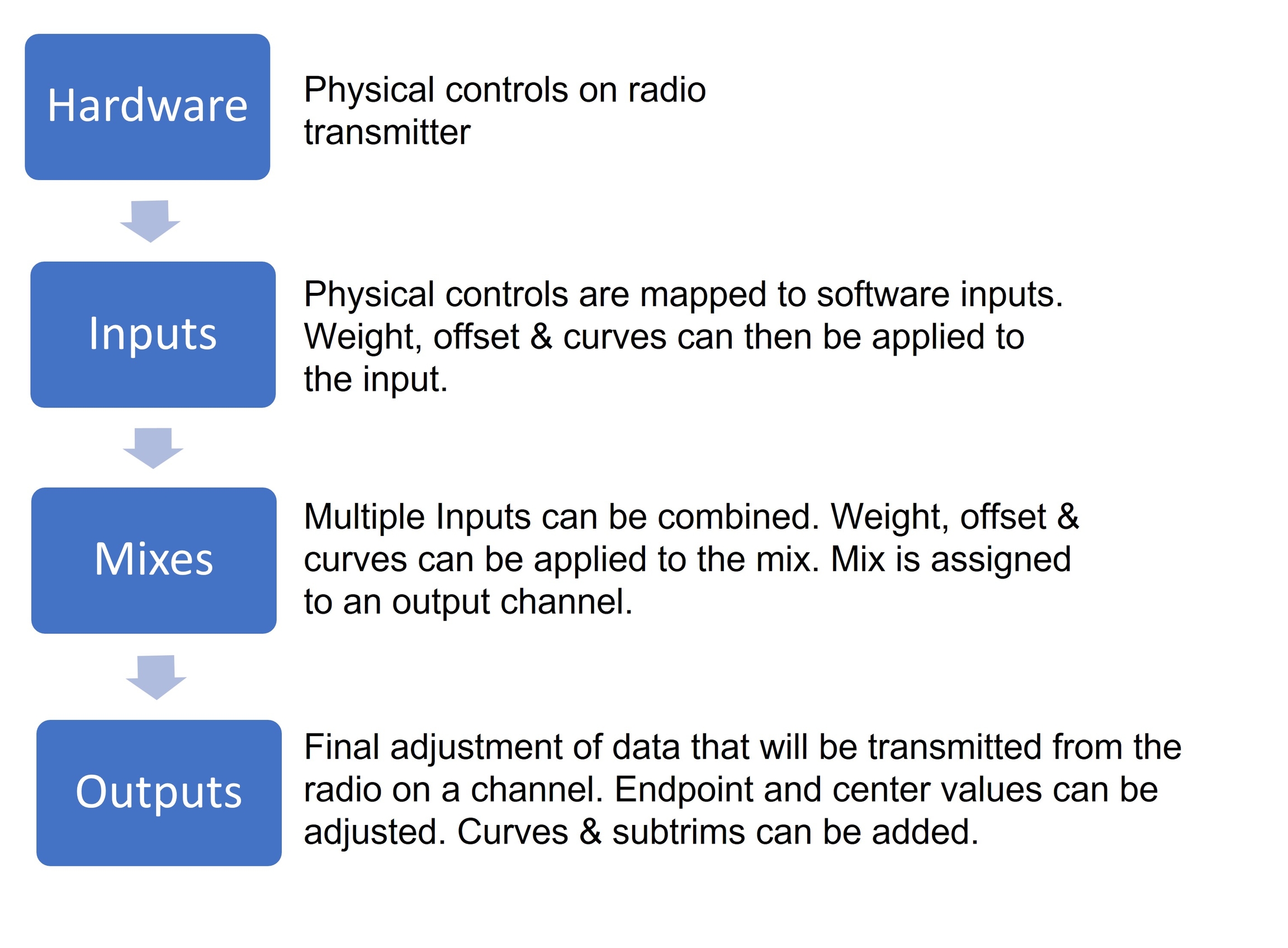
To be able to support many different types of radio transmitters, EdgeTX uses a generic control data flow that can be applied to any radio transmitter. In this data flow, any of the radio's physical controls (sticks, switches, sliders, pots) can be mapped to an input in the software. These inputs can be directly assigned or combined with other inputs into a single mix. These mixes can be modified by applying weights, offsets, and curves and are then assigned a channel for output. Final adjustments to the control data are made (including subtrims, curves, endpoint, and center values) before finally sending the control data to the RF module. The flowchart below depicts a visual summary of this control data flow. Detailed information about the flow is provided in the following sections Inputs, Mixes, and Outputs.
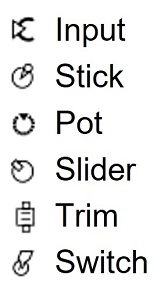
EdgeTX uses the icons below to designate different types of sources.
Below is a summary of changes that affect the user interface and/or how EdgeTX functions. It does not cover all bug fixes. For a complete list of changes (including bug fixes), please read the release notes.
Support for next generation radios (based on H5/H7 microcontrollers) which will bring much faster color LCD and black & white radios, with lots more RAM and flash in order to bring new features and functionality (#5228)
Can now use u-blox native binary protocol (rather than only NMEA) if adding a GPS to your handset ()
When editing telemetry sensor ratios, you can also see the percentage value to help give the value meaning ()
Update to Lua 5.3 (was previously 5.2) - which saves some RAM, and also allows for binary compatibility with Companion (meaning .luac files created using simulator on the PC are now compatible with the handset) ()
ELRSv4: Master/CRSF trainer option to use ELRS backpack to relay head tracker data as inputs ()
ELRSv4: support for optional arming method that frees up CH5 ()
For radios with customizable switches, you can now easily create a virtual 6POS group, as well as have groups of switches - GRx ()
Haptic on power on can now be disabled ()
Radio can be configured to automatically power off if left inactive ()
Sticky logical switch state can be configured to persist across reboots ()
USB joystick support for Android game pad functionality ()
Even shorter power on/off delay option - 0.5 seconds ()
Precision setting for mix delay up & down (in addition to the precision for "slow up/down" that was added in 2.10) ()
Radio user interface performance is significantly improved from that of 2.10 ()
Top bar widget sizes can be changed ()
File browser popup has filters to let you jump through the lists ()
Full screen Lua widget "App mode", which gives widgets focus to allow for touch and key input ()
Collapsible sections in radio setup tab to make it shorter ()
'Set Screen' special function that lets you switch to a (configured) telemetry screen ()
Displays PPM value in channel monitor (in addition to 0.0/0.00 value) ()
Flight modes allow you to have different trim settings for each flight mode. Once multiple flight modes are configured, you can adjust the trim settings in each flight mode without affecting the trim settings in other flight modes (unless they are configured to do so). There are 9 possible flight modes to use, with Flight Mode 0 being the default flight mode.
The Flight Mode screen displays an overview of each flight mode. The highlighed flight mode designates the active flight mode. Selecting a flight mode will take you to the configuration page for that flight mode.
Check FM Trims: When the check FM trims button is pressed, the trims for the current flight mode are temporarily disabled. This is used to test the impact of the current flight mode’s trims on the outputs.
The flight mode conifiguration screen has the following options:
Name: The custom name for the flight mode. If configured, this name will be shown on the lower center position of the main screen between the trims.
Switch: The trigger to enable that flight mode. It can be a switch, pot, telemetry, trim or logical switch. This option is not shown on FM0, as it is always active unless another flight mode is specifically enabled.
Fade in: Gradually change the trim value when this flight mode is enabled. Specify the time in seconds (0.0 - 25.0) until the value change is completed.
Fade out: Gradually change the trim value when this flight mode is disabled. Specify the time in seconds (0.0 - 25.0) until the value change is completed.
Trims: To configure the trims, select the trim that you want to configure to make sure that it is turned on (yellow). Then select the flight mode (0-8) that will provide the initial trim value and modifier (= or +) from the drop-down menu. When 3P is selected instead of the flight mode (0-8), the trim will act as a 3 position momentary switch.
Modifier - there are two possible value modifiers = and +. The = modifier uses the trim value directly from the selected flight mode. The + modifier uses the trim value from the selected flight mode and then adds the trim value from the flight mode you are configuring.
Example 1: If you are configuring FM1 and set the value to =0, FM1 will have the trim value of the current value of the same trim in FM0. In this case, changes made to the trim in FM1 will also affect the trim in FM0 and vice-versa.
Example 2: If you are configuring FM1 and set the value to +0, FM1 will have the trim value of the same trim in FM0, plus any trim changes made while in FM1, In this case, changes made to the trim in FM1 do not affect the trim in FM0. However, changes to trim values FM0 will affect trim values in FM1.
General model settings
The model setup page is the default page for model settings and is where you start to configure your model. It contains the following settings:
Enter the desired name for the model. The maximum number of characters is 15.
Here you may assign a label from your defined label list. By default, the model label will be Unlabeled. More information on creating labels can be found on the page.
When the folder icon is selected, a window will pop up allowing you to select an image file from the images folder on your SD Card.
The Statistics screen presents you with statistics regarding radio usage. All data is reset once the radio is powered off. The following information is provided:
SES - The amount of time that the radio has been turned on.
THR - The amount of time that the throttle has been above the 0% stick position.
TH% - The amount of time that the throttle has been above the 50% stick position.
Long pressing the [Roller] or [Dial] button will reset the Statistics and Debug screens.
Pressing [PAGE>] will take you to the Debug screens.
The Debug screen provides data points used by the developers when debugging issues in the software. Most users will not find the information useful on this screen unless debugging issues with developers. The following debug information is provided, and may change depending on handset capabilities and options configured.
Free mem - Current free radio memory in bytes.
Lua scripts
[D] - Maximum Lua duration in milliseconds.
The Channel Monitor shows both the output value (top bar) and mix value (bottom bar) for each of the 32 radio channels, spread across 4 pages of 8.
The 5th page of the channel monitor is the logical switches monitor. On this page, you will see the status (activated/non-activated) of all logical switches. Logical switches that are activated are highlighted.
Before making any updates to your radio, we ALWAYS recommend that you back up your current SD Card contents using the following steps.
With your radio powered on, plug your radio into your computer via USB. When prompted by your radio for the USB mode, select USB Storage.
With your computer, copy the entire contents of your SD card to a safe place on your computer. You can use these files again if you need to roll back the update.
If you're here reading this, you probably got stuck with something either while trying to update or after updating. So checkout the list of issues and possible resolution steps below, to see if something matches the problem you are having. If there isn't, either join us on (there is usually someone around who can help out), drop by our forum, or the if that is more your thing.
Make sure when you plug the radio into the computer, that your handset is
The Tools page in Radio Settings is where you can select Lua script-based tools for execution. Lua scripts that are located on the SD card in the Tools folder will be listed here. Selecting a tool will execute it in full-screen mode. By default, EdgeTX includes several tools. Other tools can be downloaded and added to the SD card as well. The following tools are included in the default EdgeTX SD card.
The Model Locator tool helps to find a lost model based on the RSSI (if still available). The widget produces an audio representation (variometer style) of the RSSI from the lost model. The widget will also display the RSSI in a visible colorized bar (0-100%).
The Statistics screen presents you with statistics regarding radio usage. Except for Battery, all data is reset once the radio is powered off. The following information is provided:
Session - The amount of time that the radio has been turned on.
Battery - The amount of time that the radio has been on since the last reset.
The below options can be configured for sensors:
Name: Name of the sensor - up to 4 characters.
Type: Options are custom or calculated. Custom sensors are defined by the hardware. Calculated sensors are a sensors whose value is calculated using other sensors values. See below for more information on calculated sensors.
The Outputs screen of Model Settings is where final adjustments to the control data are made (including subtrims, curves, endpoint, and center values) before finally sending the control data to the RF module. This is where the channel center, limits (to prevent servo binding) and output direction are set.
The output screen shows all the configured output channels. For each output line, it displays the values for the minimum and maximum limits, subtrim, center point, subtrim mode and channel monitor. The two options below are also available on the output page:
The Heli Setup page in Model Settings is an optional page that is available on custom-compiled versions of EdgeTX. The heli setup page is often used for collective pitch mixing (CCPM) used in flybared helicopters where the receiver directly controls the swashplate servos. Most flybarless helicopters do not need to configure this page. The outputs of the CCPM mixer are CYC1, CYC2, and CYC3, which need to be assigned to an output channel on the Mixes screen.
The heli setup page has the following configuration options:
Swash Type - Swash type for your model. Options are 120, 120x, 140, and 90.
The Model Settings screen contains all the options to configure your model. Across the top of the page you will see icons that will take you to different pages of model settings when selected. The default screen for model settings is the screen.
The icons at the top of the screen include (in order from left to right):
The Theme screen allows you to apply different colored themes to your radio. By default, the EdgeTX SD card comes with the themes shown above. Long pressing on a selected theme will give you the following options:
Set Active - Sets the selected theme as the active theme.
Edit - Opens the theme editor to edit the selected theme.
The Trainer screen is where you can configure the CPPM passthrough mode and method. When enabled, this allows the CPPM signals from a radio in Slave mode to be passed through to another radio in Master mode which will then pass the signal to the model it is connected to. CPPM passthrough can be used for several different use cases, such as: connecting a head tracker, Instructor / Student training mode, and controlling complex models that require more stick inputs than available on a standard transmitter.
Master mode - This is the mode for the radio that will be connected to the model. This radio also shall configure the special/global function (Trainer) to activate the passthrough mode. When the passthrough mode is activated, the CPPM signals from the radio in Slave mode will be sent to the model for control.
Slave mode - This is the mode for the radio that will pass it's CPPM values to the radio in Master mode, which are then sent to the model.
Below are the possibile configuration options:
EdgeTX has to possibility to select a specific source and trim for the model throttle and allows for the following configuration options:
Reverse: When enabled, this option reverses the output direction of the configured throttle channel.
Source: The source that will be used for the throttle.
Trim idle only: When enabled, the throttle trim will only affect the bottom portion of the throttle band.
Selecting Reset from the pop-up menu will give you the following options:
Reset session - When selected, this option:
Resets all timers configured with a persistence setting of Flight to zero.
Resets all discovered telemetry sensor values.
The Display screen is where you configure the telemetry screens shown when pressing the [Tele] button from the main screen.
You can configure up to Four telemetry screens. You can choose one of the following display types for each screen:
Nums (Numbers) - The numbers type displays the number value of the selected telemetry sensor or other configured object. The screen will be divided into two columns with four rows - each cell can display the data from a different sensor or object. On the display screen, the top bar will show the model name, radio battery voltage, and time in addition to the configured cells. If Timer1 is configured in the model, then it will replace the model name in the top bar.
Bars - The Bars type displays a bar graph representing the value of the selected telemetry sensor or other configured object. The screen will be divided into four rows - each row can display the data from a different sensor or object. For each sensor, you must define the minimum and maximum values for the bars. On the display screen, the top bar will show the model name, radio battery voltage, and time in addition to the configured cells. If
The Trainer screen in Radio Settings is used to configure how the radio in Master mode will handle the signals from the radio in Slave mode. It contains the below configuration options.
For each of the four main control inputs (Ail, Ele, Thr, Rud), the following options can be configured (for each row, from left to right).
Mode - How the radio in Master mode will handle the signals from the radio in Slave mode.
OFF - Stick values from the radio in Master mode will be used - no input from the radio in Slave mode.
Global functions are special functions that apply to all models on the Radio. They are configured exactly as model Special Functions and the same functions are available. For more information about configuring Global Functions, refer to the section as they are essentially the same.
To be able to support many different types of radio transmitters, EdgeTX uses a generic control data flow that can be applied to any radio transmitter. In this data flow, any of the radio's physical controls (sticks, switches, sliders, pots) can be mapped to an input in the software. These inputs can be directly assigned or combined with other inputs into a single mix. These mixes can be modified by applying weights, offsets, and curves and are then assigned a channel for output. Final adjustments to the control data are made (including subtrims, curves, endpoint, and center values) before finally sending the control data to the RF module. The flowchart below depicts a visual summary of this control data flow. Detailed information about the flow is provided in the following sections , , and .
Reset session - When selected, this option:
Resets all timers configured with a persistence setting of Flight to zero.
Resets all discovered telemetry sensor values.
Download and extract the EdgeTX SD card content for your radio type to your computer. The SD card contents can be found here: https://github.com/EdgeTX/edgetx-sdcard/releases
The list below shows which .zip file to use for different radio types:
c480x272.zip (480x272 Horizontal Color Screen) - TX16s, T16, Horus x10s,Horus x12s, most color screen radios...
c480x320.zip (480x320 Horizontal Color Screen)
c320x480.zip (320x480 Verticle Color Screen)- FlySky Nirvana NV14, EL18
bw128x64.zip (128x64 BW Screens) -All monochrome screen radios except X9D series.
bw212x64zip (212x64 BW Screens) - X9D, X9D Plus, X9D Plus 2019
Copy the extracted files to your radio's SD card. If asked, overwrite the existing files. This will only update the SD card files that are part of the default EdgeTX installation. It will not modify or delete any additional files you have added (LUA scripts, sound files, images, custom themes, model files, radio setup file, etc) that are already existing on the SD card.
Download the desired sound pack (https://github.com/EdgeTX/edgetx-sdcard-sounds/releases), unzip and copy to the "Sounds" folder on your SD card. If asked, overwrite the existing files.
Download the current EdgeTX firmware. You can download the latest release .zip file (edgetx-firmware-vX.X.X.zip) directly from Github - https://github.com/EdgeTX/edgetx/releases/latest
Unzip the file and save the correct .bin file (same name as your radio type) to the "Firmware" folder on the SD card for your radio.
Turn on your radio and navigate to the SD card screen. Open the "Firmware" folder and select the EdgeTX firmware file that you just copied to your SD card. Once the file is selected, select the option to "Flash bootloader". The bootloader will be updated.
Exit back to the main screen and then shut off your radio.
Boot your radio in bootloader mode by holding trim switches T4 and T1 to center while pushing the power button on.
You will see the EdgeTX bootloader. Select the option "Write Firmware". Select the EdgeTX firmware file that you saved to your SD card. Long-press to flash it.
After the flashing is complete, select "Exit". The radio will restart and you should be greeted with "Welcome EdgeTX".
Unit: The unit for the sensor. This unit is used when the sensor value is displayed on the screen or read aloud.
Precison: Specifies the number of digits after the decimal point when the sensor value is displayed on the screen. The number is truncated based on this setting.
Ratio: Specifies the ratio value to multiply with the sensor value as needed by some sensors.
Offset: Specifies the offset value to add to the sensor value.
Auto Offset: When selected, the first received value is used as offset. You can use the Reset telemetry option to reset the offset on already configured sensors.
Positive: When selected, the value of the sensor will be displayed only when it is a positive number. Displays zero when the sensor value becomes a negative number.
Filter: When selected, the sensor value becomes a rolling average of the last 5 received values.
Logs: When selected, the value of this sensor will be saved in the log file. SD Card logging is configured in Special Functions or Global Functions.
Calculated sensors contain the additional configuration options:
Formula: Type of calculation to use. Options include:
Add: Add the values of up to 4 designated sensors.
Average: Calculates the average value of up to four designated sensors.
Minimum: Find the minimum value of up to 4 designated sensors.
Maximum: Find the maximum value of up to 4 designated sensors.
Multiply: Multiplies the value of 2 sensors.
Totalize: Calculate the cumulative value of one sensor.
Cell: This is the formula for FrSKY Lipo battery sensor. It displays cell voltage specified by the number in "Cell index" field. If you specify "Lowest" in "Cell index" field, the voltage of the cell with the lowest is displayed. If you specify "Highest" in "Cell index" field, the voltage of the cell with the highest is displayed. If you specify "Delta" in "Cell index" field, the voltage difference between lowest and highest cell is displayed
Consumpt: Calculates the power consumption (mAh) by cumulatively add the values of current sensor.
Distance: Calculates the distance between the receiver and the radio using GPS sensor and altimeter values.
Source 1, 2, 3, 4: The sensors that will provide the argument values that are used in the formula defined above.
Persistent: When selected the sensor values will be saved when switching between models or powering down the radio.
Triggers the same checks as loading the model - i.e. throttle position, switch state, is failsafe set check, display pre-flight checklist if configured, stuck keys test, etc.
Reset timer 1 / 2 / 3 - Resets only the selected timer to zero regardles of the configured persistence setting.
Reset telemetry - This option resets all discovered telemetry sensor values.
PPM_US can be used instead of percentage values (#4987)
Widgets can now have up to 10 options (was previously 5) (#5365)
To submit new How-to articles, please prepare your article in MS Word, Google Doc or Markdown format. For consistency, please use screenshots from the EdgeTX simulator for pictures. Picture resolution should be 480 x 272 pixels if possible. Submit your article as an issue with the proposed article attached. From there it will be reviewed and once accepted, added to the knowledge base by one of the Editors. If you would like to work on one of the requested How-to articles from the issues list, please make a comment in the issue that you are working on it so that nobody else does as well. Once complete, attach your work to the issue for review.
To make a recommendation for a future How-to article, please make an issue via Github.
If you would like to contribute a translated version of the user manual, please create an issue in the EdgeTX/edgetx-user-manual repository and attach the translated manual (in .pdf format) to it. Alternately, you can create your own GitBook account, clone the English manual on your account and translate it. If you choose this way, you can simply attach the GitBook link to the issue.
Custom Scripts

Triggers the same checks as loading the model - i.e. throttle position, switch state, is failsafe set check, display pre-flight checklist if configured, stuck keys test, etc.
Reset timer 1 / 2 / 3 - Resets only the selected timer to zero regardles of the configured persistence setting.
Reset telemetry - This option resets all discovered telemetry sensor values.


Global functions are special functions that apply to all models on the Radio. They are configured exactly as model Special Functions and the same functions are available. For more information about configuring Global Functions, refer to the Special Functions section as they are essentially the same.
Pressing the [PAGE>] button will take you to the Trainer screen.
Model Independent and Model Dependent audio!
These are sounds that are not special to any specific model, and are located in /SOUNDS/language and /SOUNDS/language/SYSTEM on your radio's SD card/on-board storage when correctly configured.
The files in /SOUNDS/language/SYSTEM are automatically played by the radio in response to specific events, such as turning the radio on, telemetry being lost, switches being in the wrong position, etc.
You can also add Play Track Global Functions that will play in response to whatever trigger condition you wish.
These are sounds that are specific to a given model, and are located in /SOUNDS/language and /SOUNDS/language/model_name on your radio's SD card/on-board storage when correctly configured.
The files in /SOUNDS/language are available for use with Play Track Special Functions, and will play in response to whatever trigger condition you configure.
In addition to the Play Track Special Function, there is also the ability to configure audio be played by simply placing audio files into a directory with the same name as the model.
For example, for English, with a model named Ruxus 5, you would create a folder named /SOUNDS/en/Ruxus_5/ (note the need to replace spaces with underscores).
Then, just create/copy audio files (of the correct format!) for any of the following trigger events into that folder.
Will be played after the startup switch checks are completed when turning the radio on or when switching to the configured model.
Filename: name.wav
Played on change of switch position.
Filename structure: switchID-position.wav
SA-up.wav
SA-mid.wav (if position present)
SA-down.wav
Played on change of switch position.
Filename structure (hyphens added for clarity): P-switchNumber-position.wav
P11.wav (Pot 1, position 1)
P16.wav (Pot 1, position 6)
Played when the logical switch changes state.
Filename structure: switchID-condition.wav
L1-up.wav (true)
L1-down.wav (false)
Played on entering or exiting flight mode.
Filename structure: modeName-condition.wav (Note: No spaces in the flight mode name)
ABC–off.wav
ABC–on.wav
bw212x64.zip (212x64 BW Screens) - X9D, X9D Plus, X9D Plus 2019
TMix max - Maximum mixer task duration.
Free stack - [Menu] / [Mix] /[Audio]
[Menu] - Minimum free stack memory for menu tasks.
[Mix] - Minimum free stack memory for mixer tasks.
[Audio] - Minimum free stack memory for audio tasks.
Tlm RX Err - Numer of received telemetry errors
Does your radio have a boot / DFU button? Check the Access DFU and Bootloader Mode page to see if your handset is one of those listed where you need to hold a button down when plugging the USB in.
You could be facing driver issues. If you are on Windows, you could firstly try the ImpulseRC Driver Fixer tool. Alternately, you could go to the STMicroelectronics website, and download their free STM32CubeProgrammer tool, which includes the necessary drivers, and works with all the major operating systems. It does however require creating a (free) account at the the STMicroelectronics website, but it is the official tool for programming the micro-controller being used in all supported radio handsets.
Check with another USB cable... not all cables are created equally, and some cables are "charge only" cables.
Firstly, double check that you selected the correct name / target for your handset. Some incorrect selections will still boot, but buttons and controls will work incorrectly, or the screen will be upside down. Other combinations simply won't work at all, or make the radio seemingly go crazy, and you need to unplug the battery to get it to turn off. If you flashed the wrong target, simply go to EdgeTX Buddy, select the correct radio model, and flash the firmware.
Some handsets can have the wrong option bits set on the microcontroller, and as a result, will refuse to boot with EdgeTX 2.10 or later. The exact cause of this is unknown, but the fix is relatively simple. See the (collapsed) instructions below for more information.
If you are really stuck, you can follow this guide on how to unbrick your radio.
The Spectrum Analyzer tool will show the strength of signals in the 2.4GHz band. It uses the internal MULTI-Module as a 2.4GHz spectrum analyzer.
The display shows frequencies on the 2.4GHz spectrum, from 2400MHz to 2480MHz. The X (horizontal) axis shows the frequency in MHz and the Y (vertical) axis shows relative signal strength.
T: Frequency at the center of the plot (fixed at 2440MHz) S: Bandwidth of the plot (fixed at 80MHz) T: Position of the cursor (vertical line)
Pressing ENT and scrolling left and right allows the T value to be changed, which will move the vertical line to highlight a specific frequency.
The Wizard Loader tool assists you in setting up a new model by running a setup wizard for a particular model type. Once the model type is selected, the wizard will take you through a series of prompts and then configure your selected model based on the information provided.
NOTE: The wizard does not create a new model, it only configures the currently selected model. You must manually create a new model first and then run the wizard. If you run this wizard on an already configured model, it will overwrite your model settings!
Throttle - The amount of time that the throttle has was above the 0% stick position.
Throttle % - The amount of time that the throttle has was above the 50% stick position.
Timer - The current values of Timer 1, Timer 2, Timer 3.
The debug screen provides data points used by the developers when debugging issues in the software. Most users will not find the information useful on this screen unless debugging issues with developers. The following debug information is provided.
TMix max - Maximum mixer task duration.
Free mem - Current free radio memory in bytes.
Lua scripts
Duration(ms) - Maximum Lua duration in milliseconds.
Interval(ms) - Maximum Lua interval in milliseconds.
Script(B) - Memory used by LUA scripts.
Widget(B) - Memory used by LUA widgets.
Extra(B) - Memory used by LUA bitmap functions.
Free stack
[Menu] - Minimum free stack memory for menu tasks.
[Mix] - Minimum free stack memory for mixer tasks.
[Audio]
Add all Trims to Subtrims - When selected, adds the current trim value to the subtrim value for each configured output. The trim value is then reset to zero.
Extended Limits - When enabled, it increases the minimum and maximum range for the output values to -150 and 150. Extended limits are necessary if the full range of the control surface cannot be reached with standard limits.
Selecting an output line will give you the following options:
Edit - Opens the output configuration screen.
Reset - Sets the subtrim value back to zero. The trim value is not changed.
Copy Sticks to Subtrim - Adds the current value of the stick deflection as the subtrim value.
Copy Trims to Subtrim - Adds the current trim value to the subtrim value. The trim value is not changed.
The output configuration screen has the following configuration options:
Name - Name for the Output up to 6 characters.
Subtrim - The subtrim value (max 100). It can also be set to a global variable by pressing the "GV" button and then selecting the desire global variable from the dropdown menu.
Min - Minimum output limit. Commonly used to prevent servo binding on models that use servos for the control surfaces. This line will be shown in bold and highlighted if the input for this channel is in the lower half of the range.
Max - Maximum output limit. Commonly used to prevent servo binding on models that use servos for the control surfaces. This line will be shown in bold and highlighted if the input for this channel is in the upper half of the range.
Inverted - Select this option if you want to invert the output value.
Curve - Specify the custom curve (in any) that you want to use for this output. See for more information about custom defined curves.
PPM Center - Specify the pulse-width value for the center value of the output channel (between 1000 - 2000). Changing this will shift the entire output range, including upper and lower limits.
Subtrim mode - Defines how the subtrim value affects the min/max output values. There are two options:
Center Only - Only the center value shifts and the upper and lower limits do not change. The reaction of the stick differs between the upper half and the lower half from midpoint.
Symmetrical - the upper and lower limits will shift according to the shift of the center value. The reaction of the stick is the same on both sides of the midpoint.

Long. cyc. source - Select source input.
Lateral cyc.source -Select source input.
Coll. pitch source - Select source input.
Weight - Percentage value of the stick travel to use.
Duplicate - Makes a copy of the selected theme.
Delete - Deletes the selected theme.
Selecting the Details button will open the Edit Theme Details screen. Here you can edit the name, author and description of the them.
To edit a theme in the Theme Editor, select the color variable from the list on the left side of the screen. Once you do, the Edit Color screen will be shown.
Select the color using either the color scales on the left side of the screen. You can choose between the RGB and HSV color scales with the buttons at the upper right side of the screen.
Once you have your desired color, press the theme logo in the upper left corner to go back to the Edit Theme screen to select another color variable to edit. Once you are finished, press the theme logo to exit the Theme Editor and save your changes.
Off - Trainer mode is not used for this model.
Master / Jack - Master mode using a cable connection.
Slave / Jack - Slave mode using a cable connection.
Channel Range - This is the range of channels that will be sent to the radio in Master mode. Channel 10 is the recommended last channel to use.
PPM Frame - The first field is the length of the PPM frame. The second field is the stop length/delay between pulses. The dropdown is to select the polarity of the signal. The frame length is automatically adjusted to the correct value when the number of transmitted channels is changed. However, this automatically assigned value can be manual changed. Note: In most cases, the default setting does not need to be changed.
Master / Bluetooth - Master mode using a Bluetooth connection (if installed in radio).
Slave / Bluetooth - Slave mode using a Bluetooth connection (if installed in radio).
Master / Multi - Master mode using an additional externally mounted Multi-protocol module for the connection. For more information on this setup, see Set-up wireless trainer with a Multi -protocol module
Trim switch: The trim switch that will be used to trim the throttle. It is possible to substitute the throttle trim switch with the aileron, rudder, or elevator trim switches.
[MDL] - Model Button - Short press [MDL] button from the main screen to go to the Model Select page of the Models menu
[RTN] - Return / Back - Short press [RTN] button to return to the previous page, previous menu or cancel action
[PAGE>] / [PAGE<] - Page next & page previous - Used to navigate between different screens, tabs, or options settings, depending on the screen.
[TELE] - Telemetry - Press the [TELE] button to go to the configured telemetry screens. More information about the telemetry screens is found in the Display section.
[Roller] or [Dial] - Next & previous value The roller is used to navigate through menu options.
[Enter] - Accept - Used to select option, function or accept value - Push [Roller] or [Dial] button to select or enter.

Script- The Script type executes the telemetry Lua script that is configured. The telemetry Lua script must be located in the SD card folder: SD Card->Scripts->Telemetry in order to be available to be configured.
To configure the screens, scroll to the screen you want to configure and then press the [Enter] button. Then scroll to select the type of screen that you want to use and press the [Enter] button to select it. Depending on the selected screen type, you can then configure the telemetry objects for each cell by scrolling to the desired object and selecting it by pressing the [Enter] button. After all desired cells are configured, press the [Return] button to exit out of the configuration menu.
VERS - Firmware version
NAME: Firmware Codename
DATE - Date & time the firmware was compiled
To view the build options that were enabled when compiled, highlight the [Firmware options] options and press the [Enter] button.
To view the Modules / RX Version information about the activated RX modules for the currently selected model, highlight the [Modules / RX Version] option and press the [Enter] button.

+= Adds the stick values from both the radios in Master and Slave modes.
:= Replaces the stick values from the radio in Master mode with the stick values from the radio in Slave mode. (Default)
Weight - Percentage of stick travel to use of the radio in Slave mode. Use negative values to change the stick direction.
Source channel - The channel from the radio in Slave mode that is mapped the control input.
Multiplier - This value changes the weight of all the sticks together.
Cal (calibrate)- Sets the center stick value of the radio in Slave mode.
Pressing the [PAGE>] button will take you to the Hardware screen.
Create Model - This option creates a new model with the default configuration options.
Restore Model - This option creates a new copy of a selected model that has been previously backed up.
Pressing [Enter] on an occupied model slot that is not the active model (not marked with an asterix *) will give you the following options:
Select Model - this option selects this model as the active model.
Backup Model - This option makes a copy of the model in the Backup folder on the SD Card.
Copy Model - This option makes an exact copy of the model and allows you to select which model slot it will be placed in.
Move Model - This option allows you to move the selected model to a different model slot.
Delete Model - This option deletes the selected model.
Pressing [Enter] on an occupied model slot that is the active model (marked with an asterix *) will give you the following options:
Move Model - This option allows you to move the selected model to a different model slot.
Copy Model - This option makes an exact copy of the model and allows you to select which model slot it will be placed in.
Backup Model - This option makes a copy of the model in the Backup folder on the SD Card.
Pressing the [PAGE>] button will take you to the Setup screen.
In order to update from OpenTX to EdgeTX you will need to have both OpenTX & EdgeTX Companion installed on your computer. You can download OpenTX Companion from: https://downloads.open-tx.org/2.3/release/companion/. You can download EdgeTX Companion from: https://github.com/EdgeTX/edgetx/releases (File name: edgetx-cpn-[operation system]-[version].zip)
Turn on your radio, navigate to Radio Settings, Hardware and scroll down to the bottom of the screen and select EEPROM backup. If you do not have this option, then your radio does not store your data in EEPROM and this step can be skipped.
With your radio powered on, plug your radio into your computer via USB. When prompted by your radio for the USB mode, select USB Storage.
With your computer, copy the entire contents of your SD card to a safe place on your Computer. If you ever decide to go back to OpenTX you can use these files again. If you backed up your EEPROM in the step above, check the EEPROM folder to make sure that there is a recent backup file in there.
Start OpenTX Companion.
Select the Backup radio to file icon from the left side of the screen as shown below. Select a saving location (desktop is fine) and give it a descriptive name.
After the file has been saved, close OpenTX Companion.
Delete the contents of the Model folder on your SD Card so it is empty.
Unplug the radio from the computer and power it off.
With the radio powered off, plug your radio into your computer via USB. This will connect your radio to the computer via DFU mode.
Go to this website:
Select the Firmware version and Radio model - then Flash via USB.
On the next screen, select the STM32 Bootloader device and click Next.
If the STM32 Bootloader device is not present, then select Add New Device. From the pop up window, select STM32 Bootloader and click Connect.
After selecting the STM32 Bootloader device and clicking Next, you will be presented with a confirmation screen to verify your settings. Once you have verified everything is correct (Version, Radio, and device) click the Start Flashing button.
EdgeTX buddy will now start the flashing sequence. A progress screen will be displayed to show you the progress.
Once the flashing is complete, select the setup your SD Card link from the completion screen which will take you to the SD Card content screen.
At this point, the EdgeTX bootloader and firmware have been installed on your radio. The next step is to install the SD Card contents.
Unplug the radio from the computer and power it on. You should see the EdgeTX Splash screen on the radio, but you will still hear "Welcome to OpenTX". This is normal - we will install the EdgeTX sound pack with the SD card contents next.
With the radio turned on, plug it in to your PC via USB and select USB Storage when the option is displayed on the radio. Click on the Select SD Card option and then navigate to your EdgeTX SD card.
The EdgeTX SD Card will be mounted as a USB Drive on your computer. Select the USB Drive (notice the OpenTX files are still in there - that is the correct one.) and then click on Select folder.
On the SD Card Content screen, verify the Firmware version and Radio model are still correct, then select the desired language for the sound pack. Click on Apply Changes. A status window will pop up and show you the installation progress. Once the installation of the files is complete, the status window will close.
At this point, you now have the EdgeTX Bootloader, Firmware and the SD card contents installed. The last step is to convert your models over from OpenTX and put them on the radio. You can now close EdgeTX Buddy.
Open EdgeTX Companion. If you have not already done so, create a radio profile for your radio and make sure that it is selected as active.
In the upper left corner of Companion, select File, then Open, then select the OpenTX Backup file that you made at the very beginning. A warning message will be displayed. Click OK.
You will then see all your models from OpenTX in EdgeTX Companion. Click on the Write models and Settings to Radio button. It will warn you that it will overwrite all the models on your radio. Click Yes.
The models and settings will be written to the radio. A message will be displayed when complete. Click on OK. Unplug your radio from the USB port and close EdgeTX Companion.
All of your models have been updated to the EdgeTX .yml format and you have the EdgeTX sound pack installed. You are now ready to use EdgeTX.
Global variables are variables whose values are shared across all the configuration screens of a model. Their values can be used in weights, offsets, differential, expo settings, outputs, and in logical switch comparisons. The Global Variables screen of Model Settings shows the value of each global variable for each flight mode.
Selecting a global variable from the global variable screen will give you the following options:
Edit - Opens the global variable configuration screen for the selected global variable.
Clear - Clears the global variable values for all flight modes for the selected global variable.
The global variable configuration screen is where you assign a value and other configuration options to a global variable. Additionally, you can select how the value of the global variable is defined for every flight mode - either the value is manually defined or inherited from another selected flight mode. It contains the following configuration options:
Name - Name for the global variable. Three characters are allowed. If left blank, it will use the default GV# as the name.
Unit - (optional) Allows you to add a % label to the displayed values when selected. It DOES NOT affect how the values are calculated.
Precision - Allows you to select the number precision options whole numbers (0.-) and decimal (0.0). The default value is 0.-
Custom (Mixes) Scripts take one or more values as inputs, do some processing in Lua code, and output one or more values. Each model can have several Mixes Scripts associated with it, and these scripts are run periodically. They behave similarly to standard EdgeTX mixers, but at the same time they provide a much more flexible and powerful tool.
Typical use cases:
replacement for complex mixes that are not critical to model function
complex processing of inputs and reaction to their current state and/or their history
filtering of telemetry values
If the script output is used as a mixer source , and the script is killed for whatever reason, then the whole mixer line is disabled! Exercise caution when using them for primary controls. It is advisable to have a fallback mixer line, that will be used if for whatever reason the Mixer Script is terminated.
Here is an example of mixer script that accepts a source and constant value, and has two outputs that will be selectable in the mixer as sources.
The Version screen displays information about the current EdgeTX version that is being used:
FW - Firmware name
VERS - Firmware version
DATE - Date firmware was compiled
TIME - Time firmware was compiled
OPTS - Build options that were enabled when compiled.
The Modules / RX Version gives you information about the activated RX modules for the currently selected model.
The Screen settings section of EdgeTX is where you can customize your main views and add additional views (up to 10 in total). When selecting Screen Settings from the main navigation menu it will open Main view 1. If other main views have been added, you may select them from the number tab at the top of the screen to adjust their settings. All main view tabs have the following configuration options and are configured individually:
Layout - Selects the screen layout for the widgets. It is possible to divide the screen in up to two columns and up to 4 rows, with a widget in each cell.
Setup Widgets - see below.
Top bar - Toggles whether the top widget bar will be visible on the selected main view.
Flight mode - Toggles whether the flight mode name (if configured) will be visible on the selected main view.
Sliders - Toggles whether the slider bars will be visible on the selected main view.
Trims - Toggles whether the trim bars will be visible on the selected main view.
Mirror - Toggles whether to mirror the selected widget layout.
Selecting the user Interface button to the left of the Main view 1 tab will open the user interface configuration screen. It contains the following options:
Top bar Setup Widgets button - Sets up the widgets that will be displayed on the top bar. See below for information on how to setup widgets.
Widget Size - Allows you to configure the width of the widget zones to be shown in the top bar, at the expense of the number of widget zones you can have.
Theme - Applies the selected theme to EdgeTX. A preview of the theme is below the dropdown. EdgeTX comes with several themes installed. Additional themes to download as well as instructions for creating your own themes can be found here:
Selecting the setup widgets button will display the main view or top bar with the widget cells outlined in a hashed line. You can assign a widget to a cell by selecting the cell and then the widget you want to assign to it from the drop-down menu. After selecting the widget, it will then open the configuration options for the widget for further configuration. Widget descriptions and configuration options for widgets included with EdgeTX are below.
Pressing the [SYS] button from the Main view will open the Tools screen.
The Tools page in Radio Settings is where you can select Lua script-based tools for execution. Lua scripts that are located on the SD card in the Tools folder will be listed here. Selecting a tool will execute it. By default, EdgeTX includes several tools. Other tools can be downloaded and added to the SD card as well. The following tools are included in the default EdgeTX SD card.
The Wizard Loader tool assists you in setting up a new model by running a setup wizard for a particular model type. Once the model type is selected, the wizard will take you through a series of prompts and then configure your selected model based on the information provided.
NOTE: The wizard does not create a new model, it only configures the currently selected model. You must manually create a new model first and then run the wizard. If you run this wizard on an already configured model, it will overwrite your model settings!
Pressing the [PAGE>] button will take you to the SD Card screen.
The Curves screen of Model Settings allows you to define custom curves to use in the Inputs, Mixes, or Output screens. The curves screen will show all of the configured custom curves, with a graphical representation of each curve, the number of points, and the curve type.
Selecting an existing custom curve will display the following options:
Edit - Opens the curve configuration page.
Preset - Allows you to set the curve to one of the preset slope values (-45 to 45 degrees in 15 degree increments). The curve will have 5 points and smoothing is not enabled by default.
Mirror - Mirrors the selected curve.
Clear - Clears all curve values from the selected curve.
Selecting the plus button to create a new curve will give you the following options:
Edit - Opens the curve configuration page.
Preset - Allows you to set the curve to one of the preset slope values (-45 to 45 degrees in 15 degree increments). The curve will have 5 points and smoothing is not enabled by default.
Selecting Edit for a configured or unconfigured curve will open the curve configuration screen and display the following options:
Name - Name for the curve. Only 3 characters are possible.
Type - Type of curve: Options are Standard and Custom
Standard - Horizontal axis points are fixed values based on the number of points. Vertical axis points are adjustable.
The Curves screen allows you to define custom curves to use in the Inputs, Mixes, or Output screens. The curves screen will show the configured custom curves, with a graphical representation of each curve.
Selecting one of the curves or empty curve slots will open the configuration page for that curve.
The curve configuration screen has the following configurable options:
Name - Name for the curve. Only 3 characters are possible.
Type - Type of curve: Options are Standard and Custom
Standard - Horizontal axis points are fixed values based on the number of points. Vertical axis points are adjustable.
After the last configuration option (Smooth), you will automatically begin to scroll through the configured points on the curve. To change the values of the points, press the [Enter] button and then adjust the values as desired. For Standard curves, you will only be able to adjust the Y value. For Custom curves, you can adjust both the X and Y values.
Pressing the [PAGE>] button will take you to the Logical Switches screen.
The main view is the default view normally used during radio operation. This view displays information such as the model name, trim positions, transmitter battery voltage, flight mode, receiver signal strength, and Timers. A clock is also displayed in the center of the lower portion of all screens. There are five main view screens.
Screen 1 - This view displays the model name, trim positions (if trims are enabled), clock, transmitter battery voltage, flight mode, receiver signal strength, and Timers 1 and 2 (if enabled).
Screen 2 - This view displays the model name, trim positions (if trims are enabled), clock, transmitter battery voltage, flight mode, receiver signal strength, and Timer 1 (if enabled). It also has a graphical representation of the stick, pot, and switch positions. Use the [Roller] or [Dial] to scroll thru the additional pages. The second page shows the state of the .
Screen 3 - This view displays the model name, trim positions (if trims are enabled), clock, transmitter battery voltage, flight mode, receiver signal strength, and Timer 1 (if enabled). It also shows the values of output channels as a bar graph, 8 channels per page. Use the **[Roller]**or [Dial] to scroll thru the additional pages.
Screen 4 - This view displays the model name, trim positions (if trims are enabled), clock, transmitter battery voltage, flight mode, receiver signal strength, and Timer 1 (if enabled). It also shows the numerical values of the output channels, 8 channels per page. Use the [Roller] or [Dial] to scroll thru the additional pages.
Screen 5 - This view shows either the channel monitor or mixer monitor, 8 channels per page. Use the roller or dial to scroll thru the additional pages. Push the [Roller] or [Dial] button to switch between the channel monitor and mixer monitor.
Long pressing the [Roller] or [Dial] button from the main view screen will show a pop-up menu with the options below:
View Notes - Displays the configured model checklist. This option is only visible if a valid model checklist file is in the Models folder.
Reset - See page.
Statistics - See page.
About - Displays the EdgeTX firmware version being used by the radio.
EdgeTX supports the following monochrome screen radios:
BETAFPV LiteRadio 3 Pro
FrSky QX7 / QX7S / QX7 ACCESS / QX7S ACCESS
FrSky X9 Lite / X9 Lite S
FrSky X-Lite / X-Lite S / X-Lite Pro
FrSky X9D / X9D+ / X9D+ SE
FrSky X9D+ 2019 / X9D+ SE 2019
Frsky X9E / Frsky X9E Hall
iFlight Commando8
Jumper T12 / T12 Plus / T12 Pro Hall
Jumper T-Lite
Jumper T-Pro / T-Prov V2
Jumper T-14
Jumper T-20
RadioMaster MT12
RadioMaster T8 / T8 Pro
RadioMaster TX12 / TX12 Mark II
RadioMaster Boxer
RadioMaster Pocket
RadioMaster Zorro
The Trainer screen in Radio Settings is used to configure how the radio in Master mode will handle the signals from the radio in Slave mode.
For each of the four main control inputs (Ail, Ele, Thr, Rud), the following options can be configured (for each row, from left to right).
Mode - How the radio in Master mode will handle the signals from the radio in Slave mode.
OFF - Stick values from the radio in Master mode will be used - no input from the radio in Slave mode.
Add - Adds the stick values from both the radios in Master and Slave modes.
Replace - Replaces the stick values from the radio in Master mode with the stick values from the radio in Slave mode. (Default)
Source channel - The channel from the radio in Slave mode that is mapped the control input.
Weight - Percentage of stick travel to use of the radio in Slave mode. Use negative values to change the stick direction.
Cal (calibrate)- Sets the center stick value of the radio in Slave mode.
Multiplier - This value changes the weight of all the sticks together.
This How-To shows the configuration of a low voltage battery alert. Let's assume we have a model that is using a 2S Lipo RX battery. We want to configure an alerts when the battery voltage drops below 7.4V.
Ensure that telemetry data is being received by the radio and the sensors have been discovered within EdgeTX before proceeding.
Step 1: Create a logical switch that activates when the battery voltage drops below a defined value.
Press the [MDL] button to open the Model Setup screen and navigate to the Logical Switches tab. Create a new logical switch with the following configuration:
Function use a<x
V1 is the telemetry sensor that you want to use for this alert. In this example we are using the RxBt telemetry sensor
V2 is the voltage where you want the alarm to trigger
Delay is recommended to configure a delay so that battery sags will not will not cause the alarm to trigger
This logical switch will activate when the TX battery is below 7.4V for the duration of 10 seconds.
Step 2: Create a that announces the battery value once the logical switch is activated.
Press the [MDL] button to open the Model Setup screen and navigate to Tab and create a new Special function with the following configuration.
Switch: This is the logical switch that you configured in the previous step. In this example L01
Func: select the Play Value function from the drop-down so that it will announce the battery voltage when triggered
Value: Select the telemetry sensor that you configured in the previous step. In this example it is RxBt
Repeat: Set the value for how often it should repeat the announcement. In this example it is every 10 seconds
There are various reasons on why you may want to disable the touchscreen. Unintentional touches during a flight could change your model configuration which can be a risk.
Therefore we can create a global function or special function using the No Touch feature to disable and enable the touch feature. While global functions apply to all models, the special function is defined on individual models.
In the following example we use switch SF to disable the touch screen with a global function.
Customizable switches or logical switches cannot be used in global functions. But we can use a special function to enable and disable the touch screen with a customizable switch.
The Heli Setup page in Model Settings is an optional page that is available on custom-compiled versions of EdgeTX. The heli setup page is often used for collective pitch mixing (CCPM) used in flybared helicopters where the receiver directly controls the swashplate servos. Most flybarless helicopters do not need to configure this page. The outputs of the CCPM mixer are CYC1, CYC2, and CYC3, which need to be assigned to an output channel on the Mixes screen.
The heli setup screen has the following configuration options:
Swash Type - Swash type for your model. Options are 120, 120x, 140, and 90.
Swash Ring - Set the swash ring limit only as needed. 1 = maximum limit -> 100 or 0 = no limit.
Long. cyc. source - Select source input.
Weight - Percentage value of the stick travel to use.
Lateral cyc.source -Select source input.
Weight - Percentage value of the stick travel to use.
Coll. pitch source - Select source input.
Weight - Percentage value of the stick travel to use.
Pressing the [PAGE>] button will take you to the Flight Modes screen.
The Radio Settings section contains all the options to configure your radio. Across the top of the page you will see icons that will take you to different pages of radio settings when selected. The default screen for the radio settings is the Tools screen.
Icons at the top of the radio settings screen include (in order from left to right):
The Inputs screen of Model Settings is where you map your physical radio controls (for example: sticks, sliders, and pots) to a software input to be used by the radio. After the control has been mapped it is then possible to apply modifiers to the inputs such as a weight, offset or curve which will then be applied anywhere that input is used. Although it is possible to also assign switches as inputs, it is normally not needed as switch outputs seldomly need to be modified by a weight, offset or curve. By default, EdgeTX will automatically map your contoller sticks to Aileron, Elevator, Throttle, Rudder based on the default channel order defined in
Flight modes (FM) and Drive modes (DM) (on surface radios) allow you to have different trim settings for each flight/drive mode. Once multiple flight/drove modes are configured, you can adjust the trim settings in each flight/drive mode without affecting the trim settings in other flight/drive modes (unless they are configured to do so). There are nine possible Flight/Drive modes, with flight/drive Mode 0 being the default mode.
The Flight/Drive Modes Overview screen shows an overview of the configured Flight/Drive Modes. The information below is displayed for each flight mode row:
Mode #
Mode Name
A traditional 6 position switch/control is either a group of 6 switches that work together (where only one can be active at one time) or a single rotary switch that has six physical positions (detents). Some newer generation radios provide the "Customizable Switch" capability, which allows you to define type, grouping and startup state of the switches. Physically, they look like a regular 6 position switch which you will see on older handset designs, but they are much, much, more flexible.
Name: Whichever three letter name you wish to give each customisable switch.
Trims are used adjust the center position of a given stick axis. EdgeTX has the following time configuration options:
Reset - This resets all trim values to zero.
Trim Step: Defines the amount of increase/decrease in trim when the trim switch is pressed.
Course = 1.6%
Medium = 0.8%
There are model types where some or all of the trim switches on your radion are not used. Helicopters or drones with a flight controller usually don't need trims Also on many fixed wings you may not need all the 4 trims for throttle, rudder, elevator and aileron.
In the following example our model is a glider. Gliders don't need throttle trim. We also don't need the rudder trim, because we can adjust the rudder with the servo sub trim.
Gliders usually use differential on the aileron mixers. The plane rolls perfect when the differential is set to the correct value.
In this sample we will use the rudder trim buttons to adjust the differential of the ailerons. And we will be able to adjust this using the trims in flight.
Step 1: Disable the trims for rudder and throttle which are not needed. Then we can reuse them for other functionality. Enter the model menu and navigate to the page. Edit FM0 and disable the Throttle and Rudder trims. The yellow highlight color will be gone when the trims are disabled.
You can see the disabled trims also on the flight modes page. They now show a dash
The below options can be configured for sensors:
Name: Name of the sensor - up to 4 characters.
Type: Options are custom or calculated. Custom sensors are defined by the hardware. Calculated sensors are a sensors whose value is calculated using other sensors values. See below for more information on calculated sensors.
The Outputs screen is where final adjustments to the control data are made (including subtrims, curves, endpoint, and center values) before finally sending the control data to the RF module. This is where the channel center, limits (to prevent servo binding) and output direction are set.
The output screen shows all the output channels. For each output line, it displays the values for the subtrim, minimum and maximum limits, direction, curve, and subtrim mode. After the last output line is the option Trims=>Subtrims. When this option is selected, it adds the current trim value to the subtrim value for each configured output. The trim value is then reset to zero.
The support for Bluetooth in EdgeTX is limited to:
Bluetooth Trainer Mode
Bluetooth Telemetry Streaming
The following Bluetooth options are not supported.
Below are some additional useful resources
EdgeTX supports the following color screen radios:
FlySky NV14 / EL18
FlySky PL18 / PL18 EV
FrSky X10 / X10S / X10 Express / X10S Express
Wireless file access and transfers
Bluetooth joystick
To use Bluetooth, if your radio does not come as standard with a Bluetooth module fitted (thus meaning the Bluetooth option should already be enabled in the firmware) you will need a custom compiled version of EdgeTX that needs to be built with the BLUETOOTH=YES CMake flag. You can create customized versions of EdgeTX using the CloudBuild tab on the EdgeTX Buddy website.
Once the correct version of EdgeTX firmware is installed in your radio, the Bluetooth configuration options will be available on the Hardware page of Radio Settings.
The only off-the-shelf Bluetooth modules supported by EdgeTX are:
You can also create your own Bluetooth module by purchasing an ESP32 development kit and flashing it with the firmware from following project: https://btwifimod.gitbook.io/untitled/getting-started/hardware
The INAV Telemetry Viewer app can be used on your Android smartphone to view your telemetry data over bluetooth.
Bluetooth is only supported on radios that have at least one AUX serial port.
The compile time option Bluetooth will reserve one AUX port (on radios with 2 AUX ports, AUX2 is reserved for Bluetooth) and it will NOT be available in the normal user interface for other purposes.
EdgeTX Bluetooth trainer or telemetry has nothing to do with internal or external RF module Bluetooth functionality.
EdgeTX Bluetooth can NOT be used for Bluetooth joystick functionality at the moment.


Enable: Enable the Special Function to make it active


Credit: Kerget Ruslan
Credit: Roberto Domingues
Work in progress!

Min - Defines the minimum that is allowed for the global variable.
Max - Defines the maximum value that is allowed for the global variable.
Popup - When enabled, a popup message will be displayed when the value of a GV changes with the new GV value (see image below).
FM0 - The value of the global variable on Flight Mode 0.
FM1 -> FM8 - When the toggle switch is enabled or disabled, the following applies:
Toggle switch disabled - global variable value for the selected flight mode is inherited from the flight mode defined in the drop-down.
Toggle switch enabled (highlighted) - the global variable value for the selected flight mode is manually defined in the text field.

Custom - Both horizontal and vertical axes are adjustable.
Number of Points - number of points in the curve
Smooth - When enabled, connects the points with curved lines instead of straight lines
Verticle point values - Adjust the point values to make the desired curve.
Count - number of points in the curve. Press the [Enter] button to modify the number of points. Long-pressing the [Enter] button will give the following additional options:
Preset - Allows you to set the curve to one of the preset slope values (-45 to 45 degrees in 15 degree increments). The curve will have 5 points, and smoothing is not enabled by default.
Mirror - Mirrors the selected curve.
Clear - Clears all curve values from the selected curve.
Smooth - When enabled, connects the points with curved lines instead of straight lines.
The Inputs section is also commonly referred to as "Dual Rates" as it was previously called this in earlier versions of OpenTX.
Selecting the + button will show you a list of available inputs that can be configured. After selecting an input, the input configuration page for that input will open. Selecting an existing input will give you the following options:
Edit - opens the input configuration page for that input line.
Insert before - Inserts a new input line before the selected input.
Insert after- Inserts a new input line after the selected input.
Copy - copies the selected input line.
Move - selects the input line to be moved. The input is moved using one of the paste commands after a new line is selected (i.e. cut & paste).
Delete - deletes the selected input line.
Paste before - pastes the copied or moved input line before the selected input line.
Paste after - pastes the copied or moved input line before the selected input line.
The input configuration page allows you to edit the input configuation parameters. To the right of the configuration parameters, you can see a live graph that shows how your configuration options will affect the slope of the input.
Input Name - Name for the input. Four character are possible.
Line Name - Name of the individual line in the input. Multiple physical inputs can be mapped to one input by adding an additional input line under the input.
Source - The physical control used for the input. In addition to physical controls, you can also specify MAX (always returns 100), MIN (always returns -100), cyclics, trim switches, channel values and more. Moving the physical control after the source has been selected will automatically map it to that input.
Weight - Percentage value of the stick travel to use (often referred to as "rates"). In addition to percentage value, you can use other inputs, physical controls, MAX (always returns 100), MIN (always returns -100), cyclics, trim switches, channel values and more, using the "SRC" button.
Offset - The value added to or subtracted from the input source. In addition to percentage value, you can use other inputs, physical controls, MAX (always returns 100), MIN (always returns -100), cyclics, trim switches, channel values and more, using the "SRC" button.
Switch - The switch that activates the input line. If no switches are defined then it is always active.
Curve - Specifies the type of curve that will be used. The following curve options exist:
Diff - Multiplies only the range above or below the middle (0) by the specified %. In addition to percentage value, you can use other inputs, physical controls, MAX (always returns 100), MIN (always returns -100), cyclics, trim switches, channel values and more, using the "SRC" button.
Expo -The input value is changed exponentially. Increasing the % will result with a gentle slope near the middle(0). Decreasing the % will result in a steep slope near the middle (0). With a % of 0, the slope will be linear. In addition to percentage value, you can use other inputs, physical controls, MAX (always returns 100), MIN (always returns -100), cyclics, trim switches, channel values and more, using the "SRC" button.
When selecting the gear button at the bottom of the screen, the following option window will be displayed.
Side - Specifies the input range for which this line setting is valid. If you select ---, it will be valid in the entire range of Source values. If you select x>0, it will be valid in the upper half of the value of Source. If you select x<0, it will be valid in the lower half of the value of Source.
Trim - Specifies whether or not to include the trim values in this input. Additionally, you can select a different trim to use for this input.
Modes - Specifies which flight modes this input is active for.
- Long press the [SYS] button to go to the Radio Setup page.
[MDL] - Model Button - Short press [MDL] button to go to the Model Settings page - Long press [MDL] button to go to the Select Model page
[RTN] - Return / Back - Short press [RTN] button to return to the previous page, previous menu or cancel action
[PAGE>] / [PAGE<] - Page next & page previous - Used to navigate between different screens, tabs, or options settings, depending on the screen.
[TELE] - Telemetry - Short press the [TELE] button to go to the Screen Settings page
-Long press the [TELE] button to go to the Channel Monitor page
[Roller] or [Dial] - Next & previous value The roller is used to navigate through menu options.
[Enter] - Accept - Used to select option, function or accept value - Push [Roller] or [Dial] button to select or enter.
The system and model buttons have different functionalities based on what screen you are in the user interface:
In the Radio Setup screen:
Short press [MDL] navigates to the Model Setup screen
Long press [MDL] navigates to Manage Models screen
In the Model Setup screen:
Short press [SYS] navigates to the Radio Setup (TOOLS) screen
Long press [SYS] navigates to the Radio Setup (SETUP) screen
Short press [MDL] navigates to the Channel Monitor (existing function)
Long press [MDL] navigates to the Manage Models screen
In the Channels Monitor screen:
Short press [MDL] navigates to the Model Setup screen
Long press [MDL] navigates to the Manage Models screen
Short press [SYS] navigates to the Radio Setup (TOOLS) screen
Long press [SYS] navigates to the Radio Setup (SETUP) screen
In the Manage Model screen:
Short press [MDL] navigates to the Model Setup screen
Short press [SYS] navigates to the Radio Setup (TOOLS) screen
Long press [SYS] navigates to the Radio Setup (SETUP) screen
Certain radios are equipped with a touch screen. On these radios, you can interface with the menu options either with touch or physical buttons.
Touch the EdgeTX icon in the upper left corner of the screen to open the main navigation menu. Touch the desired menu option to select it.
Pressing the roller from the main screen will also open the main navigation menu. You can then scroll using the roller to the desired menu option and select it by pressing the roller.
Switch
Trim settings (RETA)
Check FM Trims: When check FM trim is pressed, the trims for the current flight/drive mode are temporarily disabled. This is used to test the impact of the current flight/drive mode’s trims on the outputs.
Selecting a flight/drive mode from the overview screen will open the configuration page, which has the following options:
Name: The custom name for the flight mode. If configured, this name will be shown on the upper left position of the main screen next to the battery voltage.
Switch: The trigger to enable that flight/drive mode. It can be a switch, pot, telemetry, trim or logical switch.
Trims - To configure the trims, select the trim that you want to configure (each column represents one trim, the name of which will be shown on the upper right of the screen when highlighted). Then scroll to select the flight/drive mode (0-8) that will provide the initial trim value and modifier (= or +). Select -- to disable the trim.
When 3P is selected instead of the flight mode (0-8), the trim will act as a 3 position momentary switch (and will be in the middle switch position when no trim button is pressed).
Modifier - there are two possible value modifiers = and +. The = modifier uses the trim value directly from the selected flight/drive mode. The + modifier uses the trim value from the selected flight/drive mode and then adds the trim value from the flight/drive mode you are configuring.
Example 1: If you are configuring FM1 and set the value to =0, FM1 will have the trim value of the current value of the same trim in FM0. In this case, changes made to the trim in FM1 will also affect the trim in FM0 and vice-versa.
Example 2: If you are configuring FM1 and set the value to +0, FM1 will have the trim value of the same trim in FM0, plus any trim changes made while in FM1. In this case, changes made to the trim in FM1 do not affect the trim in FM0. However, changes to trim values FM0 will affect trim values in FM1.
Fade in: Gradually change the trim value when this flight/drive mode is enabled. Specify the time in seconds (0.0 - 25.0) until the value change is completed.
Fade out: Gradually change the trim value when this flight/drive mode is disabled. Specify the time in seconds (0.0 - 25.0) until the value change is completed.
Global variables are variables whose values are shared across all the configuration screens of a model. Their values can be used in weights, offsets, differential, expo settings, outputs, and in logical switch comparisons. The bottom portion of the flight/drive mode configuration screen shows an overview of each global variable for the selected flight/drive mode. For each global variable row, the following information is displayed:
Global Variable Number: Displayed as GV(1-9)
Global Variable Name: User-defined name for the global variable - up to three characters.
Mode: Where the value of the global variable comes from. Options are:
Own: the global variable value for the selected flight/drive mode is manually defined in the Value text field.
FM(1-9) - global variable value for the selected flight/drive mode is inherited from the flight mode defined in the drop-down.
Value: The current value of the global variable.
You can edit the value of the global variable by changing the value in the value text field. Selecting the global variable number will open the global variable configuration screen will give you the following options:
Name - Name for the global variable. Three characters are allowed.
Unit - (optional) Allows you to add a % label to the displayed values when selected. It DOES NOT affect how the values are calculated.
Precision - Allows you to select the number precision options whole numbers (0.-) and decimal (0.0). The default value is 0.-
Min - Defines the minimum that is allowed for the global variable.
Max - Defines the maximum value that is allowed for the global variable.
Popup - When enabled, a pop-up window will be displayed on the main screen when the value of this global variable changes during normal use.
FM1 -> FM8 - Allows you to select the global variable inheritance for the flight/drive mode. Long press the field to switch between Own and Inheritence mode. In Own mode, you can define the global variable value for the selected flight mode. In Inheritance mode, you can select the Flight Mode that the global variable will inherit the value from.
Pressing the [PAGE>] button will take you to the Inputs screen.
None : basically disabled
Toggle : customizable switch is only "active" while being pushed
2POS : pushing the switch will alternate it's state. i.e. OFF push ON push OFF ....
Group: This is where you choose how the individual switches should be grouped. You can choose for them to be in a single group (the default, Group 1), and then they can be used like a traditional 6POS switch. Or, you can define them to be in seperate groups (e.g. as shown for SW1-SW3 and SW4-SW5 above), or even for some switches to not be in a group at all (e.g. SW6 as shown above). You can use the various groups as a source for inputs or mixes via the GR# option, where the # represents the number of the group (e.g. GR1, GR2).
When switches are grouped, only one switch in the group can be active at a time. Additionally, you can specify that one switch in the group must always be on "Always on".
Startup: Here is where you specify the startup state for either a 2POS customizable switch not in a group, or for a group of customizable switches. You can specify it to be "Last" (remember the last state when the transmitter was powered off or model changed) or in the up (released) or down (pressed) state.
OFF / ON Colors (on compatible handsets): Some handsets support configuring the color of the customizable switches. If so, the OFF and ON color pickers will be shown for each customisable switch (as shown below) and you will be able to pick your preferred colour for each state. Black represents when the customizable switch is not illuminated.

Fine = 0.4%
Extra Fine = 0.2%
Exponential = 0.2% near the center and the step value increases exponentially as the distance from the center increases.
Extended Trims: Increases the maximum trim adjustment value from ±25% to ±100%.
Display trims: Option to display the numerical trim value on the trim bar. Options are:
No - Does not display the numerical trim value on the trim bar
Yes - Displays the numerical trim value on the trim bar once the trim is no longer at zero.
Change - Momentarily displays the numerical trim value on the trim bar (2 seconds) once the trim is no longer at zero.
Step 2: Now we navigate to the Global Variables page and set a default value of 30 for GV1 in FM0
Step 3: We will now create 2 Special Functions to adjust the GV1 value we created in the previous step. Navigate to the Special Functions page and create a new function SF1 for decreasing GV1
Trigger is set to the Rud- (rudder trim left)
Function is Adjust
Global var is GV1
Mode is Inc/Decrement
Inc/Decrement is set to -=1
Enable the special function
We create SF2 now for increasing the GV1 value
Trigger is set to Rud+ (rudder trim right)
Function is Adjust
Global var is GV1
Mode is Inc/Decrement
Inc/Decrement is set to +=1
Enable the special function
after those 2 special functions are created you can already test the functionality. When you go to Global Variables page you can monitor the GV1 value. The value should change as you use the trims.
Step 4: Now we can adjust our aileron mixer and use the GV1 value for the differential
Curve is set to use Global variables and GV1 is selected
Now you should be able to use the Rudder trim to adjust your aileron differential in flight.

ID: This number indicates what type of sensore it is. It contains two parts. The first part is the ID number which defines the sensor type. The second part is the instance number for the hardware. If multiple sensors of the same type are configures, the instance numbers must be unique.
Unit: The unit for the sensor. This unit is used when the sensor value is displayed on the screen or read aloud.
Precison: Specifies the number of digits after the decimal point when the sensor value is displayed on the screen. The number is truncated based on this setting.
Ratio: Specifies the ratio value to multiply with the sensor value as needed by some sensors.
Offset: Specifies the offset value to add to the sensor value.
Auto Offset: When selected, the first received value is used as offset. You can use the Reset telemetry option to reset the offset on already configured sensors.
Positive: When selected, the value of the sensor will be displayed only when it is a positive number. Displays zero when the sensor value becomes a negative number.
Filter: When selected, the sensor value becomes a rolling average of the last 5 received values.
Logs: When selected, the value of this sensor will be saved in the log file. SD Card logging is configured in Special Functions or Global Functions.
Calculated sensors contain the additional configuration options:
Formula: Type of calculation to use. Options include:
Add: Add the values of up to 4 designated sensors.
Average: Calculates the average value of up to four designated sensors.
Minimum: Find the minimum value of up to 4 designated sensors.
Maximum: Find the maximum value of up to 4 designated sensors.
Multiply: Multiplies the value of 2 sensors.
Totalize: Calculate the cumulative value of one sensor.
Cell: This is the formula for FrSKY Lipo battery sensor. It displays cell voltage specified by the number in "Cell index" field. If you specify "Lowest" in "Cell index" field, the voltage of the cell with the lowest is displayed. If you specify "Highest" in "Cell index" field, the voltage of the cell with the highest is displayed. If you specify "Delta" in "Cell index" field, the voltage difference between lowest and highest cell is displayed
Consumpt: Calculates the power consumption (mAh) by cumulatively add the values of current sensor.
Distance: Calculates the distance between the receiver and the radio using GPS sensor and altimeter values.
Source 1, 2, 3, 4: The sensors that will provide the argument values that are used in the formula defined above.
Persistent: When selected the sensor values will be saved when switching between models or powering down the radio.
Selecting an output line will give you the following options:
Edit - Opens the output configuration screen.
Reset - Sets the subtrim value back to zero. The trim value is not changed.
Cpy Trims -> Subtrim - Adds the current trim value to the subtrim value. The trim value is not changed.
Cpy Sticks -> Subtrim - Adds the current value of the stick deflection as the subtrim value.
Cpy min/max to all - Copies the settings in Min / Max field of selected channel to all other channels.
The output configuration screen has the following configuration options:
Name - Name for the Output up to 6 characters.
Subtrim - The subtrim value (max 100). It can also be set to a global variable by pressing the ldong-pressing the [Enter] button to switch to GV Mode and then selecting the desire global variable.
Min - Minimum output limit. Commonly used to prevent servo binding on models that use servos for the control surfaces. This line will be shown in bold if the input for this channel is in the lower half of the range.
Max - Maximum output limit. Commonly used to prevent servo binding on models that use servos for the control surfaces. This line will be shown in bold if the input for this channel is in the upper half of the range.
Direction- Select --- for normal output value, INV if you want to invert the output value.
Curve - Specify the custom curve (in any) that you want to use for this output. See Curves for more information about custom-defined curves.
PPM Center - Specify the pulse-width value for the center value of the output channel (between 1000 - 2000). Changing this will shift the entire output range, including upper and lower limits.
Subtrim mode - Defines how the subtrim value affects the min/max output values. There are two options:
△ (Center Only) - Only the center value shifts. The upper and lower limits do not change. The reaction of the stick differs between the upper half and the lower half from midpoint.
= Symmetrical - Both the upper and lower limits will shift according to the shift of the center value. The reaction of the stick is the same on both sides of the midpoint.
Pressing the [PAGE>] button will take you to the Curves screen.
FrSky X12S / X12S-IRSM
Jumper T15
Jumper T16 / T16 Plus / T16 Pro Hall
Jumper T18 / T18 Lite / T18 Pro
RadioMaster/Eachine TX16S / RadioMaster TX16S MAX / RadioMaster TX16S Mark II


To allow for the easy entry of text and numbers, EdgeTX uses virtual text and number keyboards that can be interacted by either the touchscreen or roller. Additionally, there are shortcut keys that are mapped to the hardware buttons as described below:
[SYS] = cursor left
LONG [SYS] = cursor to start
[MDL] = change keyboard mode (alpha upper, alpha lower, numbers + special, numeric)
LONG [MDL]
[SYS] = change keyboard mode (alpha upper, alpha lower, numbers + special, numeric)
LONG [MDL] = backspace
[PGDN] = cursor right
LONG [PGDN]
[SYS] = '-'
LONG [SYS] = 'MIN'
[MDL] = '>>'
LONG [MDL]
[SYS] = '<<'
LONG [SYS] = 'MIN'
[MDL] = '>>'
LONG [MDL] = 'MAX'
The Manage Models screen allows you to create new models, select which model is active, create and apply model labels, and create model templates.
The active model's name will be highlighted (yellow in this case) and displayed on the screen's top bar. Double-tapping an active model will give you the following options:
Duplicate model - This option creates an exact duplicate of the model with the same name. Changes to the model name or other settings need to be made in the tab.
Label Model - When this option is selected, all configured labels will be displayed and can be selected for this model. More Information about is below.
Save as template - this option saves a copy of the model as a model template.
Double-tapping on a non-active model (unhighlighted) will give you the following options:
Select model - this option selects this model as the active model.
Duplicate model - same as described above.
Delete model - this option moves the model to the deleted folder on the SD Card. Only models that are not active can be deleted.
To create a new model, select the New Model button in the upper right corner. You will then be presented with the following options:
Blank Model - This will create a blank model with only the default options configured.
Wizard - This will launch the new model wizard and create the model as configured in the wizard.
Personal - This option will allow you to select one of your saved model templates and then create a copy of it as a new model.
Model labels allow you to give each model one or more labels. You are then able to filter the models displayed in the Manage Models screen based on the labels that you select. This allows people with many configured models to find them easier. By default, the Favorites and Unlabeled labels are created automatically. All models are considered unlabeled until a label is applied to them.
To filter the visible models based on their labels, select the filter or filters from the left column. It will automatically filter out the models that do not have those model labels. For more information on how the filters work or to configure advanced filtering options, see:
To assign a label to a model, double-tap on the model or press [Enter] when the model is selected and then select Label Models. Once selected, all configured labels will be displayed and one or more labels can be selected for this model. Labels applied to the model will be designated with a check icon.
To create a new model label, select the New button on the bottom left of the screen. The Enter Label pop-up will appear and you can enter the desired label name. Select Save to save the new label.
Long press [Enter] or long tap on desired label and you be shown a menu with the following options:
Rename Label - change the label's name
Delete Label - Deletes the label from the label list and from all models that have it assigned.
Move Up - positions the label higher on the list
Move Down - - positions the label lower on the list
The drop-down menu below the label list is for sorting the filtered models. Models can be sorted as described below:
Name A-Z
Name Z-A
Least Used
Most Used
There are 4 layouts for the model list in the Manage Models page:
Large image (2x2) - Default layout
Small image (3x3)
Name only, 2 columns (2x6)
Name only, 1 column (1x6)
The layout can be changed by pressing the Layout button (next to the New button), which will cycle through the available layouts.
The Radio Setup screen is where you configure basic settings for your radio. It contains the following options:
Date - The current date. This date is used for the SD card log files.
Time - The current time. This time is used for the SD card log files.
Additional Settings Buttons - Additional configuration options for the named areas are available when selecting these buttons. More information about these configuration settings is on the next page - Additional Radio Settings
Splash Screen - Duration that the splash screen will be displayed.
Startup Sound - Toggles whether to enable/disable startup sound.
Pwr Off delay - The delay between when the power button is pushed and when the radio shuts off. The options are: 0s, 0.5s, 1s, 2s, 3s, 4s. It is recommended to set at least a 1s delay in order to prevent the radio from being shut off in the case of an accidental button press.
Power Auto Off - If enabled, the radio with automatically power off after the configured amount of inactivity, if there is no RF module with active telemetry, or an active trainer connection.
Power ON/OFF Haptic - When enabled, the radio with use the vibration motor to give a haptic pulse when powering the radio on (indicating when the power button can be released) and when the transmitter is powering off.
Owner ID - Custom registration ID used only for users with FrSky ISRM/ACCESS modules.
Country code - Used by some RF modules to ensure adherence to local regulatory RF requirements. Options are America, Japan, Europe.
Voice language - Language for the voice pack. This setting and the voice pack folder on the SD card must match for the sounds to be played.
Units - Units of measure. Options are metric or imperial.
PPM Units - Level of accuracy for PPM values are displyed. Options are 0.-, 0.0 or us (μs/microseconds).
Play delay (sw. mid pos) - The minimum time in milliseconds a switch must be in the middle position before a special function will get activated. This is used to prevent the middle position from being activated on a three-position switch when switching from low position to high position.
USB Mode - Sets the default action when a USB cable is plugged into the USB data port and the radio is powered on. Options are: Ask, Joystick, Storage, and Serial.
Hats Mode: how the hat switches will function (NV14, EL18 and PL18/PL18EV only).
Trims only: The Trim hat switches will be used to adjust the trim values only.
Keys only: The Trim hat switches will be used to navigate the menu options (as described below)
Switchable: Trim hat switch functionality can be changed between Trims and Keys on-the-fly.
Rotary Encoder Mode - Set to Normal by default. The Inverted option reverses the direction of the roller.
Default Channel Order - The default channel order for new models and the trainer screen. The letters stand for: A = Aileron (Roll), E = Elevator (Pitch), T = Throttle, R = Rudder (Yaw). Changing this setting does not affect existing models.
Mode - The stick mode that will be used for the transmitter. Defined by what actions the left stick takes. The options are:
Telemetry is data received from the model to the radio from various sensors. These sensors may be included in the radio receiver or flight controller or may be separate sensors, such as GPS, variometer, or magnetometer. The received telemerty data can be displayed by EdgeTX in widgets, configured in alarms or audio call-outs.
The Telemetry screen is where you configure these sensors to use in EdgeTX. Below are the following configuration options:
Sensors
All previously configured sensors are listed here. The list is collapsible by clicking on the arrow icon to the right side of the Sensors label (and is collapsed when you initially open the page). The number of configured sensors will be displayed in parentheses, ex: (6), when the sensor list is collapsed. Sensors that have not received data since the model was loaded or the telemetry values were reset display --- for the values. The asterisk * to the left of the sensor value will flash when the sensor has received a data update. A solid asterisk* indicates that the sensors that are receiving regular updates. Sensors that are no longer receiving regular updates will not be marked with the asterisk*. See for a list of commonly used sensors in EdgeTX.
The following options are listed under the sensor list.
Discover New: When selected, it will look for new sensors on the model and automatically configure them. If the sensor list is collapsed when a new sensor is discovered, the newly found sensor will be visible on the sensor list (old sensors will remain collapesd/hidden).
Add New: When selected, it will create a new blank sensor for that must be configured manually.
Delete All: This option will delete all previously configured sensors.
If you long-press the [Enter] button for a specific sensor, the following options will be displayed:
Edit: Allows you to edit the sensor's configuration options.
Copy: Creates a copy of that sensor.
Delete: Deletes that sensor.
See the page for a detailed description of all the configuration options for setting up or editing sensors.
RX Status
Here you can configure the threshold for the RX alarms. The Rx-Stats label will change (Rx-Stats, RSSI, Rqly, Sgnl) depending on the protocol that is used with the model.
Low alarm - The threshold value when the "RF signal low" voice prompt will be played. The recommended value is 45.
Critical alarm - The threshold value when the "RF signal critical" voice prompt will be played. The recommended value is 42.
Disable telemetry alarms - When enabled, no alarm voice prompts will be played.
Variometer
A variometer detects changes in the model altitude. EdgeTX can alert the user of these altitude changes by providing a rising/lower pitched tone. Use the Variometer menu on the Radio Setup page to set the actual frequency and volume of the tone to be played. The following options exist to configure the variometer alarm.
Source - Specifies the sensor to use as the variometer. It is selected from the telemetry sensors added in Sensors section.
Range - Specifies the ascent/descent range that will trigger the change in the Variometer beeping pitch. If climb/descent rate is within the range specified here, beeping pitch will change according to that value. When it goes beyond the range specified here, beeping pitch will stop changing. Units are meters/second or feet/second based on the Units setting on the Radio Setup page.
Center - Specify the range for ignoring changes in climb/descent rates. When the climb/descent rate is within the range specified here, the beeping pitch will not change.
Pressing the [PAGE>] button will take you to the Display screen.
Telemetry is data received from the model to the radio from various sensors. These sensors may be in included in the radio receiver or flight controller, or may be separate sensors, such as GPS, variometer, or magnetometer. Telemetry data that is received can be displayed by EdgeTX in widgets, configured in alarms or audio call-outs.
All prevously configured sensors are listed here. Sensors that are highlighted have received data since the model was loaded or the telemetry values were reset. A small circle icon will flash to the left of the sensor value when it has received a data update. Sensor values in black designate the sensors that are receiving regular updates. Sensor values that are red are no longer receiving regular updates. See Recognized Sensors for a list of commonly used sensors in EdgeTX.
The following options are listed under the sensor list.
Discover New: When selected, it will look for new sensors on the model and automatically configure them.
Add New: When selected, it will create a new blank sensor for that must be configured manually.
Delete All: This option will delete all prevously configured sensors. Note: This button will not be visible if there are no sensors configured.
If you select a specific sensor, you will get the following options:
Edit: Allows you to edit the sensor's configuration options.
Copy: Creates a copy of that sensor.
Delete: Deletes that sensor.
See the page for detailed description of all the configuration options for setting-up or editing sensors.
Here you can configure the threshold for the RX alarms. The Rx-Stats label will change (Rx-Stats, RSSI, Rqly, Sgnl) depending on the protocol that is used with the model.
Low alarm - The threshhold value when the "RF signal low" voice prompt will be played. The recommended value is 45.
Critical alarm - The threshhold value when the "RF signal critical" voice prompt will be played. The recommended value is 42.
Disable telemetry alarms - When enabled, no alarm voice prompts will be played.
A variometer detects changes in the model altitude. EdgeTX can alert the user of these altitude changes by providing a rising/lower pitched tone. Use the Variometer menu on the Radio Setup page to set the actual frequency and volume of the tone to be played. The following options exist to configure the variometer alarm.
Source - Specifies the sensor to use as the variometer. It is selected from the telemetry sensors added in Sensors section.
Range - Specifies the ascent/descent range that will trigger the change in the Variometer beeping pitch. If climb/descent rate is within the range specified here, beeping pitch will change according to that value. When it goes beyond the range specified here, beeping pitch will stop changing. Units are meters/second or feet/second based on the Units setting on the page.
Center - Specify the range for ignoring changes in climb/descent rates. When the climb/descent rate is within the range specified here, the beeping pitch will not change.
EdgeTX provides 3 timers that can be custom programmed. Below are the configuration options.
Name: Name of the timer
Mode:
OFF- The timer is not used
ON - The timer runs all the time
Start -The timer starts once the configured switch is activated. After the time is started, the timer ignores the switch position.
Throttle - The timer starts once the throttle is raised and the configured switch is activated. The timer will stop counting if either the throttle position is lowered back to the minimum value or the configured switch is deactivated.
Throttle % - The timer counts proportionally to the throttle. It counts in real time at full throttle and at half speed at 50% throttle.
Throttle Start - The timer starts once the throttle is raised and the configured switch is activated. After starting, the timer ignores the throttle position and will keep counting unless the switch is deactivated.
Switch- Select the switch that will trigger the timer to start. If no switch is selected, the timer will trigger based only on the configured mode. In addition to a switch, you can also select a trim, a telemetry source (triggered when telemetry data is received from that source), or physical activity (stick movement or button press) (labeled as ACT)
Start- The time used for the timer's advanced functions. The default value is 00:00 and when left as such, the timer operates like a stopwatch, counting upward until stopped. If a different time is entered in this box, then the additional Direction drop-down menu option will appear.
Direction - If set to Show Remaining, the counter will function like a countdown timer - counting down from the designated time to zero and then alerting the user. If set to Show Elapsed, the timer functions like an alarm, counting up from zero until the designated time and then alerting the user.
Minute Call - If selected, you will be notified every minute that passes as described in the Count Down option.
Count Down:
Silent - No notification is given until the timer reaches zero. When it reaches zero, you will hear one beep.
Beeps - The radio will beep every second starting at the time designated.
Voice - The radio will count down by second starting at the time designated.
Persistent:
Off - The timer value is reset when switching models or when the radio is turned off / on.
Flight - The timer value is NOT reset when switching models or when radio is turned off / on. The timer value is only reset when the Reset flight option is selected in the menu.
Manual Reset - The timer value is reset only when it is individually selected to be reset (example: Reset timer1) in the menu.
In order to setup a wireless trainer connection with the Multi-protocolm Module, you will need the following:
A student radio with a FrSky D16 capable TX module
An instructor radio with:
A Multi-protocol module to serve as the RX
An additional TX module to use to communicate with the model (protocol does not matter, but must match the protocol use by the RX on the model)
Ensure that the model is bound to the desired TX module and operational on the instructor radio.
On the Instructor radio, configure the Trainer section of Radio Settings. See section for more information on how to set this page up.
On the Instructor radio, configure the Trainer section of Model Settings. For the Mode, select Master/Multi
On the Instructor radio, configure the special function Trainer. Designate a switch to activate the mode and make sure the function is enabled.
On the Instructor radio, configure the Internal RF and External RF sections in Model Setup. The RF Module's mode that will communicate with the Student radio should be set to Multi, FRSkyRX and RF Protocol: Multi. Also, configure a receiver number. Both the Instructor and Student radios need to use this same receiver number. The other RX module should be configured to communicate with the model.
One the Student radio, configure either the Internal RF or External RF (which ever module will be used) to communicate to the Instructor radio. If using a multi-protocol module it should be set to Multi, FRSkyX and RF Protocol: D16. Configure the receiver number to the same number configured in the step above.
On the Student radio, no configuration of the Trainer section in the Model Settings or Radio Settings is necessary, leave the Mode option in the Trainer section of Model Settings configured to Off.
Trainer mode is now configured.
You can test this by watching the channel monitor on the Instructor radio, activating trainer mode via the configured switch and moving the sticks on the student radio. If configured correctly, you should see the stick movements from the student radio on the channel monitor on the Instructor radio.
Special thanks to all the people and groups that contributed (directly or indirectly) to this document.
Bill Clark - https://www.youtube.com/@the-happy-RC-flyer
John - RCvidoereviews - https://www.youtube.com/@RCVideoReviews
John Salt - https://www.youtube.com/@Rchelicopterfun
Joshua Bardwell -
Lee Schofield- Painless360 -
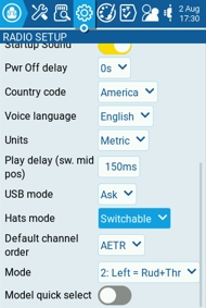
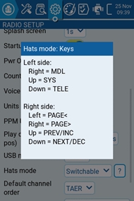
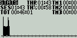
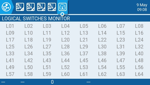
The Hardware screen is where you configure hardware specific-settings for your radio. It shows all physical hardware objects (sticks, pots, switches) and allows for their modifications. It is also where you can calibrate your sticks and pots. It also contains additional configuration options.
To calibrate your physical radio controls (sticks, pots, sliders & 6-position switch), highlight the [Calibration] option and press the [Enter] button. The radio will prompt you through the calibration steps.
The Mixes screen of Model Settings is where several Inputs can be combined into one "Channel Mix". These mixes are then assigned to a radio channel for output. This is also the place where switches, knobs or sliders are assigned to a channel for output. Similar to the Input section, it is also possible to assign a weight, offset or curve to a channel mix.
Selecting the + button will create a new mix and open the mixes configuration page. Selecting an existing mix will give you the following options:
Edit - opens the mixes configuration page for that mix line.
The Mixes screen is where several Inputs can be combined into one "Channel Mix". These mixes are then assigned to a radio channel for output. This is also the place where switches, knobs or sliders are assigned to a channel for output. Similar to the Input section, it is also possible to assign a weight, offset or curve to a channel mix.
The Mixes screen shows you an overview of your configured mixes. Each row represents a mixer line and displays the following information from left to right: channel, weight, input, mix name switch. These items are described in the area below.
Selecting an empty mix line and pressing [Enter] will create a new mix and open the mixes configuration page.
Selecting an existing mix line and pressing [Enter] will toggle between Copy/Paste mode and Move mode. In Copy/Paste mode, a copy of the mix line is made, which can be pasted into the desired channel or mix line. In Move mode, the selected mix can be moved to a different channel. Press the [Return] button to exit this mode.
The USB Joystick has two possible modes, Classic and Advanced.
In Classic mode, the radio's configured output channels will be sent to the target device in numerical order and mapped to the device's preconfigured USB controller axes and buttons. Below is the default channel mapping for Microsoft Windows.


[PGDN] = toggle case
[PGUP] (X12S) = toggle case
LONG PGDN = delete
[TELE] = cursor right
LONG [TELE] = cursor to end
[PGUP] = cursor left
LONG PGUP = cursor to start
[TELE] = toggle case
LONG [TELE] = delete
[PGDN] & [PGUP] = '<<'
LONG [PGDN] & [PGUP] = 'DEF'
[TELE] = '+'
LONG [TELE] = 'MAX'
[PGDN] = '+'
[PGUP] = '-'
[TELE]= '+/-'
LONG [TELE] = 'DEF'


Show instance ID:
Ignore Instances: This options prevents mutltiple sensors from reporting the same telemetry data.
Tone/Silent - Specifies whether to beep when climb/descent rate is within the range specified by Center.

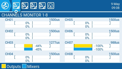
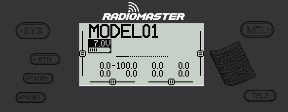
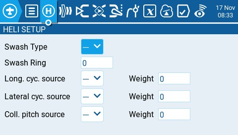
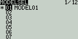
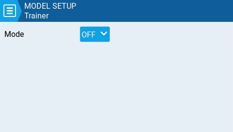

Aileron (Roll)
Elevator (Pitch)
Rudder (Yaw)
Throttle
4: Left = Ail+Thr
Aileron (Roll)
Throttle
Rudder (Yaw)
Elevator (Pitch)
1: Left = Rud+Ele
Rudder (Yaw)
Elevator (Pitch)
Aileron (Roll)
Throttle
2: Left = Rud+Thr
Rudder (Yaw)
Throttle
Aileron (Roll)
Elevator (Pitch)

3: Left = Ail+Ele
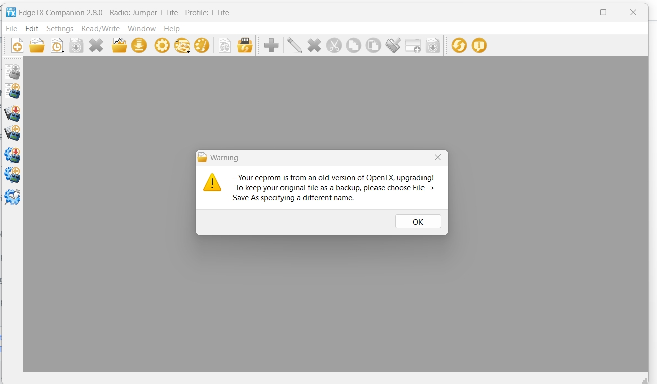
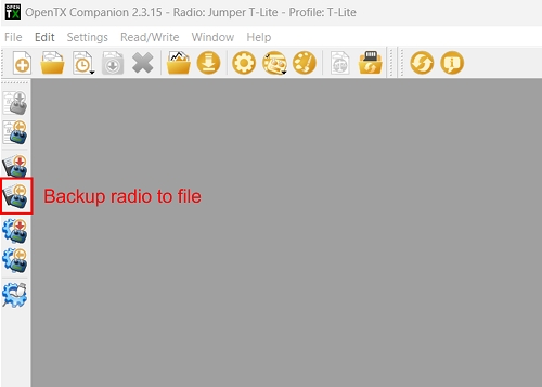
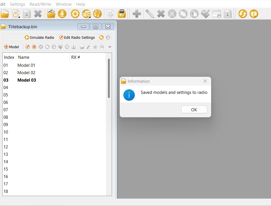
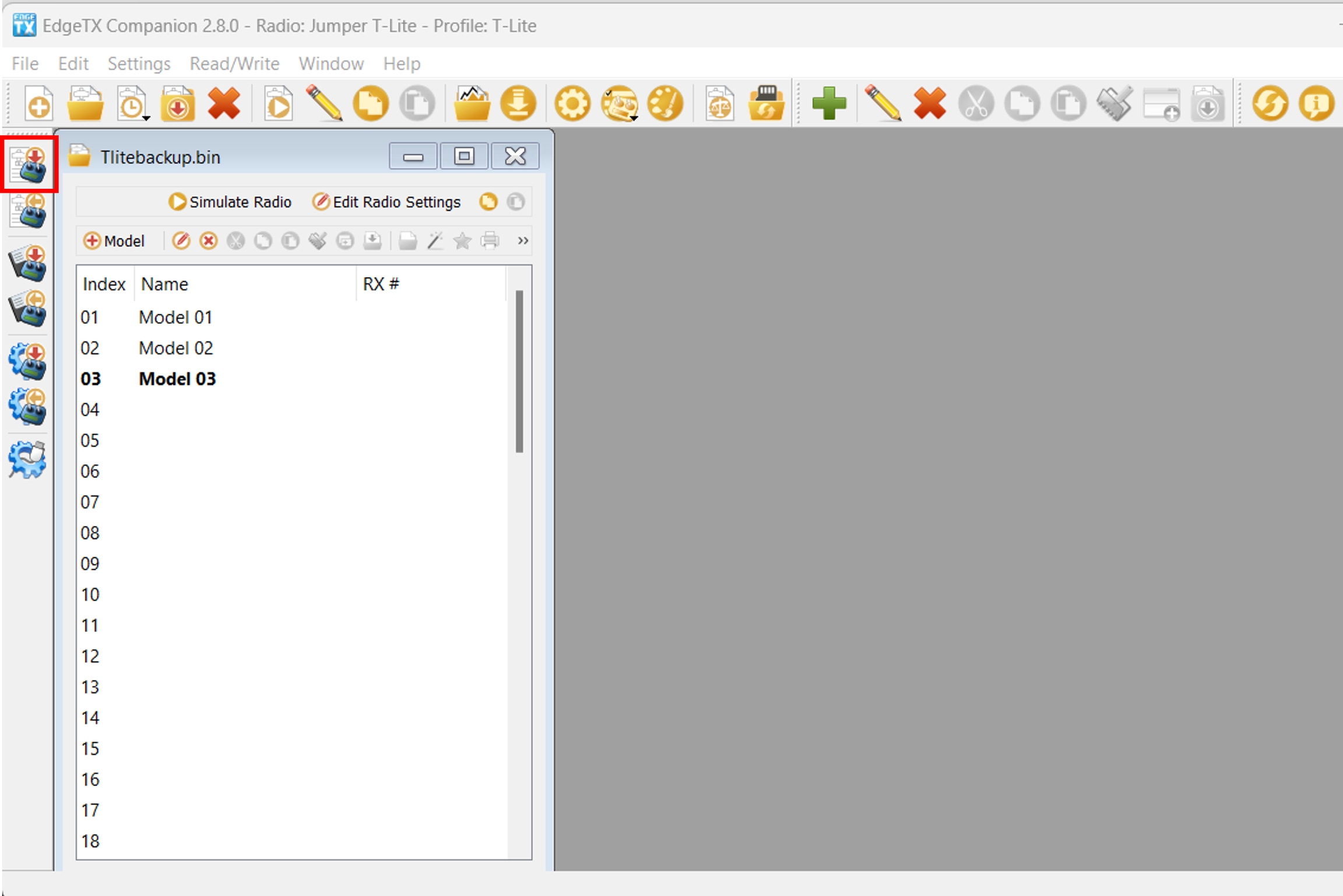
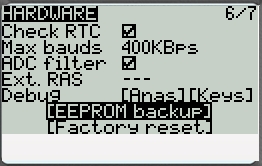
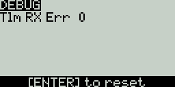
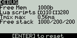
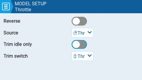
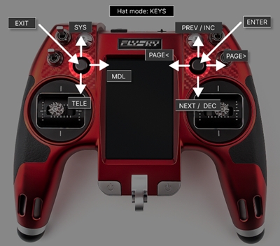
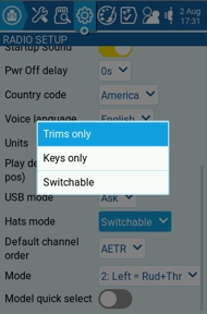
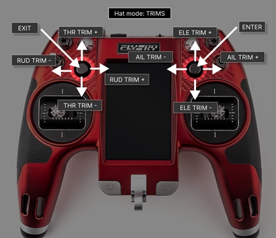
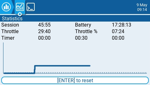
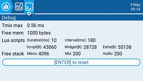
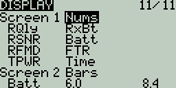
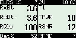
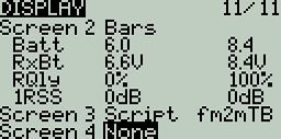
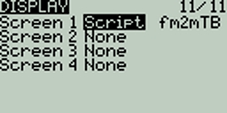
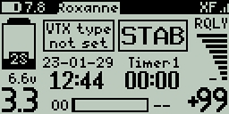
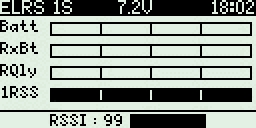
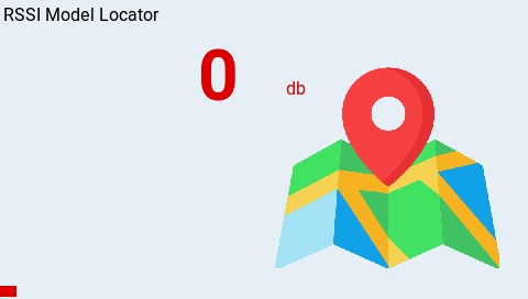
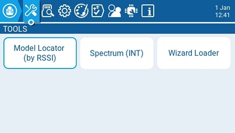

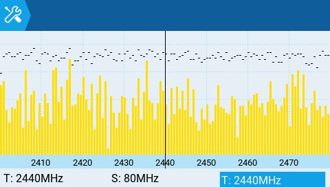


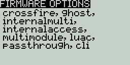
Func -
---
The slope will be linear.
X>0
The range below the middle (0) is always 0. Above the middle (0), the slope is linear.
X<0
The range above the middle (0) is always 0. Below the middle (0), the slope is linear.
Cstm - assigns a custom defined curve. See Curves for more information about custom defined curves.


Save as template - same as described above.
SoarETX_v2 - This will display the more updated v2 of the pre-configured model templates for radio-controlled model sailplanes.

No inst. (ignore instances): This option prevents multiple sensors from reporting the same telemetry data.
Tone/Silent - Specifies whether to beep when climb/descent rate is within the range specified by Center.
Beeps & Haptic - The radio will beep and vibrate every second starting at the time designated.
Voice & Haptic - The radio will count down and vibrate by second starting at the time designated.
All - Beeps when the buttons are pressed and sounds are played when there are alerts or warnings.
No Key - No beeps when buttons are pressed or the scroll wheel is turned but does play sounds when there are alerts or warnings. Also plays sounds triggered by special functions.
Alarm - Only plays alarm or warning sounds. Also plays sounds triggered by special functions.
Quiet - No Beeps or sounds are played.
Volume
The master volume for the radio.
Wav volume
The volume for alerts and warnings and sounds that are played with the Play track special function
Background volume
The volume for background .wav files (music) that are played with the BGMusic special function
Repeat Zero
The time before the tone repeats in milliseconds.
Mode - configures when the radio vibrates.
All - Vibrates when the buttons are pressed and when there are alerts or warnings.
No Key - No vibrations when buttons are the pressed or scroll wheel is turned but does vibrate when there are alerts or warnings.
Alarm - Only vibrates for alarms or warning sounds.
Quiet - No vibrations are made.
An "alarms disabled" visual warning is displayed when the transmitter is turned on if the sound mode is set to quiet.
Checks if a receiver is still connected to the radio on attempted shutdown. Makes a audio and visual alert if one is detected.
Mode
Off – Always off.
Keys – Turns on when buttons are pressed.
Ctrl – Turns on when sticks, switches, and knobs are used.
Both – Turns on when buttons, sticks, switches, and knobs are used.
ON – Always on.
The length in seconds that the backlight is on. The minimum value is 5 seconds. The maximum value is 600 seconds.
The backlight turns on when there are alarms or warnings.
The time offset from UTC where the radio is being used. Can be configured in 15 minute increments.
Adjust the transmitter's real-time clock to match the time determined by the GPS.
The GPS coordinate format that will be displayed.
The Enabled Features section of Radio Setup allows you to configure the Global settings for which tabs are visible in the Radio Setup and Model Settings area of EdgeTX. The configuration setting for the active model will show to the right of the toggle switch. The model configuration will override the global configuration.
Model quick select - Affects Manage Model screen. Both options require you first to select the desired model using the scroll wheel or short tap.
When OFF: short/long tap (short/long ENTER) on the selected model will show the menu, where you can "Select model" to set it to active.
When ON: short tap (short ENTER) on the selected model will set it active immediately. To activate the menu, make a long tap or long ENTER.
Label select - 'Multi select' or 'Single select' (Multi select is the default). If Single select is chosen then only a single label can be selected.
Label matching - 'Match all' or 'Match any' (Match all is the default). Match all is the current logic - only models having all selected labels are shown. Match any will show models with any of the selected labels.
Favorites matching - Only available when 'Match any' is selected for Label matching. Options are 'Must match' and 'Optional match' (Must match is the default). Only applies when 'Favorites' is in one of the selected labels. If 'Must match' is selected then only shows models that have Favorites AND the other selections. If 'Optional match' is selected then models that match Favorites OR any of the other labels are shown.
For your gimbal calibration, use a left-to-right & up-to-down movement for the gimbals, not a circular movement! Additionally, use the normal amount of pressure at the endpoints. Excessive endpoint pressure will cause the gimbal to be miscalibrated.
Selecting one of the Axis, Pots, or Switches lines from the list will allow you to add a 3 character label to the control as well as change the type of control as needed. Additionally, you can invert the direction of the Pots by selecting the -> at the end of the line, which will then change to <- .
Batt. Calib (Battery Calibration) - Set this value to match the transmitter battery voltage. This ensures that the displayed battery voltage is accurate.
RTC Batt - The current voltage of the RTC battery. The RTC (real time clock) battery keeps the radio's date and time accurate even when no main radio battery is present.
Check RTC - When enabled, checks the RTC battery at startup and warns you if the battery voltage is low.
Audio Mute - When enabled, puts the transmitter in mute mode until a sound needs to be played. This prevents interference noise from high-powered TX modules from coming out of the transmitter speakers.
Internal RF Type - Select the module type for the internal module bay. Options are: Multi, XJT, ISRM, CRSF. When CRSF is selected, you can also select the baud rate. You can read more about baud rates here.
Sample Mode (External RF)- Options are Normal and OneBit. The default setting of Normal should be used by most users. Only users of X9D+ and X7 radios may want to use OneBit mode.
Mode - mode that the bluetooth module will be used in. The options are:
--- - Off
Telemetry - used for sending telemtry data over bluetooth.
Trainer - used for bluetooth trainer mode
One a mode is selected, you will see the following information:
PIN Code - PIN code for bluetooth device in the radio (visible in Telemetry mode only)
Local addr - Identifying address of the bluetooth device in the radio.
Dist addr - Identifying address of bluetooth device that radio is connected to.
Name - the name the bluetooth device will be seen as.
Serial Port - Displays a list of available auxiliary serial ports that can be configured and used. The listed ports are based on the ports that are available in the particular radio hardware. The ports listed below are for example only and may not be present in your radio.
AUX1 - First available auxiliary serial port can be configured with the below options:
OFF - Turned off.
Telem Mirror - The same telemetry data that goes to the external module bay is sent to the serial port.
Telemetry In - Receive telemetry data over the serial port.
SBUS Trainer - Connect the Instructor and Student radios over the serial port.
LUA - Send/receive data to/from Lua script.
GPS - Receive GPS telemetry data over the serial port.
CLI - Send commands to the radio via the command line.
USB-VCP - Virtual COM Port. This is one of the options presented when connecting your radio to the PC with most radios. Is often set to 'CLI' for radios with internal ExpressLRS RF modules in order to do firmware updates.
ADC Filter - Enables or disables the ADC Filter. This filter can also be enabled/disabled per model in the model settings.
Ext. RAS - (Formerly SWR) Reflected antenna signal. Lower numbers are better, with a 1:1 ratio being theoretically the best. Not supported by all RF Protocols.
The debug section allows for testing and debugging of the analog controls and keys.
Debug Analogs - These screens will show you the data for your analog controls (Sticks, Sliders, Pots, 6-position switch). There are two views - Calibrated Analogs, Raw Analogs (5 Hz).
Debug Keys - This screen will show you the digital data for your keys, switches, trims, and the rotary encoder (roller).
Debug Customisable Switches (select radios) - This screen will show you the physical and logical state of the customisable switches, as well as the led state or color (if the handset supports RGB customisable switches).
Pressing the [PAGE>] button will take you to the Version screen.
Insert after - Inserts a new mix line after the selected mix.
Copy - copies the selected mix line.
Move - selects the mix line to be moved; mix is moved using one of the paste commands after a new line is selected (i.e. cut & paste).
Delete - deletes the selected mix line.
Paste before - pastes the copied or moved mix line before the selected mix line.
Paste after - pastes the copied or moved mix line before the selected mix line.
Show mixer monitors - Selecting this option will display a bar graph on the mix channels showing the current value for that mix channel.
The upper right portion of the mixes configuration page contains a channel monitor for the selected mix line. It shows the output (top) and mix (bottom) values. The following configuration options are also available:
Name - Name of the mix (optional). Up to 6 characters are allowed.
Source - The source for the mix. In addition to inputs, you can select sticks, pots, sliders, trims, physical and logical switches, heli mixer outputs, trainer import channel values, and other channels, using the "SRC" button.
Weight- Percentage of the source value to use. In addition to percentage value, you can select sticks, pots, sliders, trims, physical and logical switches, heli mixer outputs, trainer import channel values, and other channels, using the "SRC" button.
Offset - The value added to or subtracted from the source. In addition to a fixed value, you can select sticks, pots, sliders, trims, physical and logical switches, heli mixer outputs, trainer import channel values, and other channels, using the "SRC" button.
Switch - The physical switch that activates this mix line (optional). If no switch is selected, then the mix will be active by default.
Curve - Specifies the type of curve that will be used. See the curve section on the page for detailed explanations of the different curve types.
Multiplex - The multiplex setting defines how the current mixer line interacts with the others on the same channel. Add will add its output to them, Multiply will multiply the result of the lines above it, and Replace will replace anything that was done before it with its output.
Modes - Specifies which flight modes this mix is active for.
Trim - Specifies whether or not to include the trim values in this mix. For the trim values to be included, the trim field for the relevant input must also be enabled on INPUTS screen.
Warning -when selected, the radio will beep when this mix is active. You can choose from OFF (0) or beep patterns 1, 2, 3.
Delay up/dn pre (precision) - Changes the precision for Delay up/dn between 0.0 and 0.00.
Delay up - Creates a time delay in seconds between when the source value increases and when it is output.
Delay down - Creates a time delay in seconds between when the source value decreases and when it is output.
Slow up/dn pre (precision) - Changes the precision for Slow up/dn between 0.0 and 0.00.
Slow up - Adjusts the transition speed for source value increases. Specify the time to transition from -100% to + 100% in seconds. You can specify a range from 0.00 seconds to 25.00 seconds.
Slow down - Adjusts the transition speed for source value decreases. Specify the time to transition from -100% to + 100% in seconds. You can specify a range from 0.0 seconds to 25.0 seconds.

Selecting an existing mix line and long-pressing [Enter] will give you the following options:
Edit - opens the mixes configuration page for that mix line.
Insert before - Inserts a new mix line before the selected mix.
Insert after - Inserts a new mix line after the selected mix.
Copy - copies the selected mix line.
Move - selects the mix line to be moved.
Delete - deletes the selected mix line.
The right portion of the mixes configuration page contains a graph that shows the channel range for the mix.
When the edit option is selected for a mix, the following configuration options are available:
Mix Name - Name of the mix (optional). Up to 6 characters are allowed.
Source - The source for the mix. In addition to inputs, you can select sticks, pots, sliders, trims, physical and logical switches, heli mixer outputs, trainer import channel values, and other channels. Long press [Enter] to bring up the list of available source categories.
Weight- Percentage of the source value to use. In addition to physical controls, you can also specify MAX (always returns 100), MIN (always returns -100), cyclic, trim switches, channel values, global variables and more. Moving the physical control after the source has been selected will automatically map it to that input. Long press [Enter] to bring up the list of available source categories.
Offset - The value added to or subtracted from the source. In addition to physical controls, you can also specify MAX (always returns 100), MIN (always returns -100), cyclic, trim switches, channel values, global variables and more. Moving the physical control after the source has been selected will automatically map it to that input. Long press [Enter] to bring up the list of available source categories.
Trim - Specifies whether or not to include the trim values in this mix. For the trim values to be included, the trim field for the relevant input must also be enabled on INPUTS screen.
Curve - Specifies the type of curve that will be used. See the curve section on the page for detailed explanations of the different curve types.
Switch - The physical switch that activates this mix line (optional). If no switch is selected, then the mix will be active by default.
Warning -when selected, the radio will beep when this mix is active. You can choose from OFF or beep patterns 1, 2, 3.
Multiplex - The multiplex setting defines how the current mixer line interacts with the others on the same channel. Add will add its output to them, Multiply will multiply the result of the lines above it, and Replace will replace anything that was done before it with its output.
Modes - Specifies which flight modes this mix is active for. Visible modes are active.
Delay prec (precision) - Changes the precision for Delay up/dn between 0.0 and 0.00.
Delay up - Creates a time delay in seconds between when the source value increases and when it is output.
Delay down - Creates a time delay in seconds between when the source value decreases and when it is output.
Slow prec (precision) - Changes the precision for Slow up/dn between 0.0 and 0.00.
Slow up - Adjusts the transition speed for source value increases. Specify the time to transition from -100% to + 100% in seconds. You can specify a range from 0.00 seconds to 25.00 seconds.
Slow down - Adjusts the transition speed for source value decreases. Specify the time to transition from -100% to + 100% in seconds. You can specify a range from 0.00 seconds to 25.00 seconds.
Pressing the [PAGE>] button will take you to the Outputs screen.
Ch1 - X Axis
Ch 2 - Y Axis
Ch 3 - Z Axis
Ch4 - X Rotation
Ch 5 - Y Rotation
Ch 6 - Z Rotation
Ch 7 - Dial
Ch 8 - Slider
CH 9 - Ch 32 - Buttons 1 - 24
In Advanced mode you can configure the following options:
Interface mode: This indicates to the target device (the device you are connecting your transmitter to) what type of device you are connecting. The options are Joystick, Gamepad, MultiAxis.
Circular cutout: For axis pairs (X-Y, Z-rX): By default, the range of the axis pairs is a rectangular area. With this option, the axis will be limited to a circular area (like gamepad controllers commonly are). Options are : None or X-Y, Z-rX or X-Y, rX-rY or X-Y, Z-rZ
Output channels 1-32
Mode: For each output channel, you can select the mode that you want to use for that channel. The available options are None, Btn, Axis, Sim.
None - Channel is not used
Btn - Channel is used to simulate a button. Configuration options include:
Inversion - Inverts the output channel signal. Options are: On / Off
Button Mode -
Normal - Each postion of a multiposition switch is represented by a button. The current switch state is represented by a continous button press.
Pulse - Similar to "Normal" mode. However, instead of continous button press it is represented by a short button press.
SWEmu - The toggle switch emulations a push button. The first press turns the virtual button on, the second press turns it off.
Delta - The change of the output channel is represented by 2 buttons. While the output value is decreasing, the first button is pressed. When the output value is increasing, the second button is pressed. If there is no change, then no buttons will be pressed.
Companion - This option should be selected when using your transmitter to control the simulator in EdgeTX Companion. It allows the multi-position switches to function properly in the simulator.
Positions - The type of button that will be simulated.
Push - will only map to one button
2POS - 8 POS - will map to the number of buttons that the switch has (ex: 3POS will map to 3 buttons).
Button No: The button number that the output will be mapped to and sent to the target device as.
Axis - The channel is used to simulate an axis and will be mapped to one of the target device's default axes.
Axis options are: X, Y, Z, rotX (rotation x), rotY, rotZ
Sim - The channel is used to simulate a common sim axis and it will be listed on the target device as the selected option (ex: Thr)
Sim Axis options are: Ail, Ele, Rud, Thr, Acc, Brk, Steer, Dpad


Not all radios go into Bootloader or DFU mode the same way. Below you will find descriptions how to get into Bootlader and DFU mode for many EdgeTX radios.
Bootloader: Turn off the radio transmitter. Press the Bootloader button and Power button, release at the same time.
DFU: Turn off the radio transmitter. Press and hold the DFU button and plug in the USB cable, release the DFU button.
Bootloader: Turn off the radio transmitter. Pull both trims inward and press both power buttons.
DFU: Turn off the radio transmitter. Press and hold the DFU button and plug in the USB cable, release the DFU button.
Bootloader: TODO
DFU: TODO
Bootloader: Turn off the radio transmitter. Pull both horizontal trims (T1 and T4) inwards, and press the power button.
DFU: Turn off the radio transmitter. Turn the radio over so you are looking at the back of it. Remove the left side battery cover. Use a non-conductive (i.e. plastic) object to press and hold the DFU button down, and plug in the USB cable. Release the DFU button. The cooling fan will be running at full speed if you have done this correctly.
Bootloader: Turn off the radio transmitter. Pull both horizontal trims (TR7 and TR8) together and press both power buttons.
DFU: Turn off the radio transmitter. Press and hold the DFU button and plug in the USB cable, release the DFU button.
Bootloader: Turn off the radio transmitter. Pull both horizontal trims (TR3 and TR4) together and press the power button.
DFU: Turn off the radio transmitter. Press and hold the DFU button (circled in the image below) and plug in the USB cable, release the DFU button.
Bootloader: Turn off the radio transmitter. Press the Boot button and Power button, release at the same time.
DFU: Turn off the radio transmitter. Conect the USB cable from your computer to your radio. Hold down the Boot button, then push and hold the Power button. The screen will stay dark, the LEDs will run from left to right. Radio is now in DFU mode.
Bootloader: Turn off the radio transmitter. Pull both horizontal trim switches together and press the power button.
DFU: Turn off the radio transmitter. Plug in the USB cable to the USB port on the top of the radio.
Bootloader: Turn off the radio transmitter. Pull both horizontal trim switches together and press the power button.
DFU: Turn off the radio transmitter. Press and hold the DFU button and plug in the USB cable, release the DFU button.
Bootloader: Turn off the radio transmitter. Pull both horizontal trim switches together and press the power button.
DFU: Turn off the radio transmitter. Press and hold the DFU button and plug in the USB cable, release the DFU button.
Bootloader: Turn off the radio transmitter. Push both trim hat switches inward together and press the power button.
DFU: Turn off the radio transmitter. Press and hold the DFU button and plug in the USB cable, release the DFU button.
Bootloader: Turn off the radio transmitter. Push both the two inner horizontal trim buttons together and press the power button.
DFU: Turn off the radio transmitter. Plug in the USB cable.
Bootloader: Turn off the radio transmitter. Push both trim hat switches inward together and press the power button.
DFU: Turn off the radio transmitter. Press and hold the DFU button and plug in the USB cable, release the DFU button.
Bootloader: Turn off the radio transmitter. Pull both horizontal trim switches together and press the power button.
DFU: Turn off the radio transmitter. Plug in the USB cable to the USB port on the top of the radio (power button LED should light up). Press and hold SG (top left shoulder switch) and then press and release the power button (only needs a momentary press). You can now release SG.
Bootloader: Turn off the radio transmitter. Pull both trims T1 and T2 together and press the power button.
DFU: Turn off the radio transmitter. Plug in the USB cable to the side USB port (under the rubber cover).
Bootloader: Turn off the radio transmitter. Push both trim hat switches inward together and press the power button.
DFU: Turn off the radio transmitter. Plug in the USB cable to the USB port on the top of the radio.
Bootloader: Turn off the radio transmitter. Pull both horizontal trim switches together and press the power button.
DFU: Turn off the radio transmitter. Plug in the USB cable to the USB port on the top of the radio (power button LED should light up). Momentarily press the SYSTEM (SYS) button for the TX15 to enter the DFU mode.
Bootloader: Turn off the radio transmitter. Pull both horizontal trim switches together and press the power button.
DFU: Turn off the radio transmitter. Plug in the USB cable to the USB port on the top of the radio.
Bootloader: Turn off the radio transmitter. Pull both horizontal trim switches together and press the power button.
DFU: Turn off the radio transmitter. Plug in the USB cable to the USB port on the top of the radio.
Logical Switches are virtual two-position switches whose values (ON/OFF or +100/-100) are based on the evaluation (true/false) of a defined logical expression. Once configured, logical switches can be used anywhere in EdgeTX that a physical switch can be defined.
The Logical Switches page in Model Settings shows you all the configured logical switches as well as an overview of their configured options.
Selecting the + button will allow you to select an unused logical switch to configure.
Selecting a configured logic switch will give you the following options:
Edit - Opens the Logical Switches configuration page for the selected logical switch.
Copy - Copies the selected logical switch
Paste - Pastes a copied logical switch onto the selected logical switch. Note: it will overwrite the selected logical switch.
Clear - Deletes all configuration options for the selected logical switch.
After selecting to edit a logical switch, you will have the following configuration options:
Func - The logical function that you want to use. See below for a description of the possible functions you can use.
V1 - The first variable in the expression to evaluate.
V2 -The second variable in the expression to evaluate.
In the expression, a and b represent sources (sticks, switches, etc.), and x represents the constants (values) to be compared.
Before making any updates to your radio, we ALWAYS recommend that you back up your current SD Card contents using the following steps.
With your radio powered on, plug your radio into your computer via USB. When prompted by your radio for the USB mode, select USB Storage.
With your computer, copy the entire contents of your SD card to a safe place on your computer. You can use these files again if you need to roll back the update.
With the radio powered off, plug your radio into your computer via USB. This will connect your radio to the computer via DFU mode.
Go to this website:
Select the Firmware version and Radio model - then Flash via USB.
On the next screen, select the STM32 Bootloader device and click Next.
If the STM32 Bootloader device is not present, then select Add New Device. From the pop up window, select STM32 Bootloader and click Connect.
After selecting the STM32 Bootloader device and clicking Next, you will be presented with a confirmation screen to verify your settings. Once you have verified everything is correct (Version, Radio, and device) click the Start Flashing button.
EdgeTX buddy will now start the flashing sequence. A progress screen will be displayed to show you the progress.
Once the flashing is complete, the next step is to update your SD card. It is not always necessary to update your SD card contents. However, it is recommended. To update your SD card contents, select the Setup your SD Card link from the completion screen, which will take you to the SD Card content screen.
Unplug the radio from the computer and power it on.
With the radio turned on, plug it in to your PC via USB and select USB Storage when the option is displayed on the radio. Click on the Select SD Card option and then navigate to your EdgeTX SD card.
The EdgeTX SD Card will be mounted as a USB Drive on your computer. Select the USB Drive and then click on Select folder.
On the SD Card Content screen, verify the Firmware version and Radio model are still correct, then select the desired language for the sound pack. Click on Apply Changes. A status window will pop up and show you the installation progress. Once the installation of the files is complete, the status window will close.
If you were not able to flash your firmware with EdgeTX Buddy, follow the steps below to flash the firmware with the bootloader. Keep your radio connected to your computer via USB and in USB storage mode.
Navigate back to the Radio Firmware tab.
Select the Firmware version and Radio model - then Download .bin.
After the firmware is downloaded, you will be asked for the location to save the file. Navigate to the radio's SD card and select the Firmware folder. Then select Save.
Disconnect the USB cable from the radio and turn off the radio.
Boot your radio into bootloader mode by holding trim switches T4 and T1 to center while pushing the power button on.
You should now see the EdgeTX bootloader. Select the option Write Firmware. Select the EdgeTX firmware file that you saved to your SD card. Long-press to flash it.
After the flashing is complete, select Exit. The radio will restart with the updated EdgeTX version.
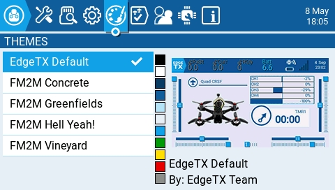
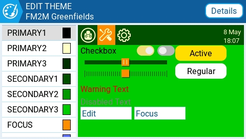
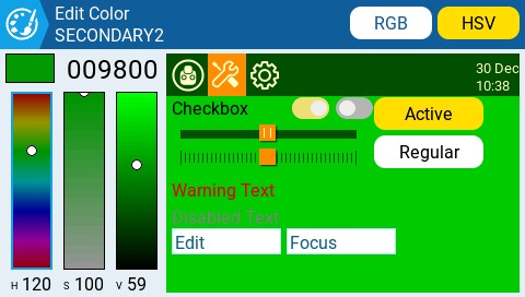
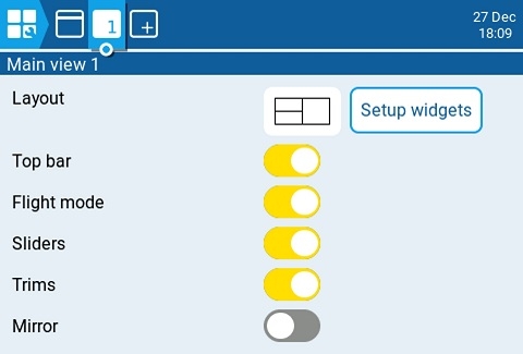
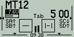
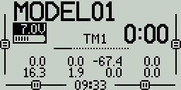
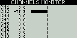
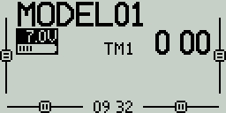
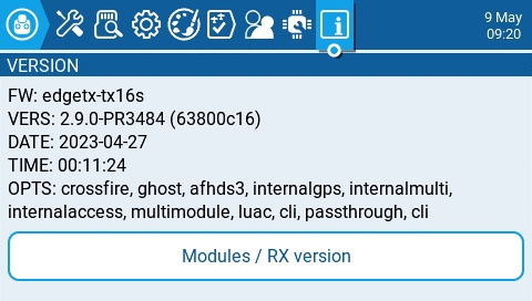
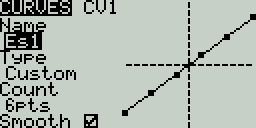
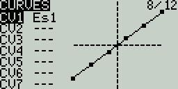
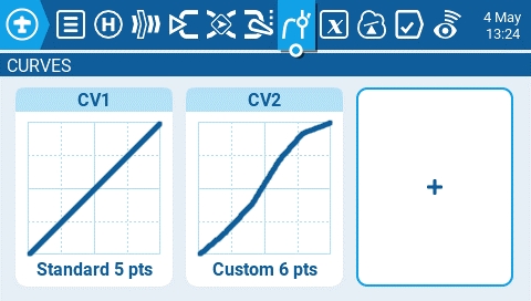
The configuration settings for both the Internal and External RF pages work the same. The only difference is that the Internal RF section is for configuring the built-in module and the External RF section is for configuring an RF module in the external module bay.
The Internal / External RF modules are "active" for a model when the buttons are yellow and inactive when they are white.
The receiver number is a user-assigned number for a model that is sent to the receiver when bound. Each model must have a unique receiver number. However, models using different protocols may have the same receiver number without issues. EdgeTX will inform you when a receiver number is unique or if it is already being used with a text above the number field.
The Special Functions section is where you can configure the special functions that are included in EdgeTX. These special functions add additional functionality beyond normal model controls, such as enabling trainer mode, playing a sound, adjusting the radio backlight, adjusting radio volume, etc. On the special functions screen, you will see all configured special functions as well as some of the configured options such as function name, activation switch, if the function is enabled, and other configuration options.
To configure a special function, select the desired special function row and press the [Enter] button. Then, scroll with the [Roller] to select the attribute that you want to edit (it will be highlighted) and press the
The following sensors are commonly used and normal automatically detected by EdgeTX:
Logical Switches are virtual two-position switches whose values (ON/OFF or +100/-100) are based on the evaluation (true/false) of a defined logical expression. Once configured, logical switches can be used anywhere in EdgeTX that a physical switch can be defined.
The Logical Switches page shows you all the configured logical switches as well as an overview of their configured options.
Selecting a logic switch will give you the following options:
Edit - Opens the Logical Switches configuration page for the selected logical switch.
The Hardware screen is where you configure hardware specific-settings for your radio. It contains the following configuration options:
Battery meter range - Sets the maximum and minimum voltage for the battery meter. This should be set based on the type of battery you are using.
Battery Calibration - Set this value to match the transmitter battery voltage.
Check RTC voltage - When enabled, checks the RTC battery at startup and warns you if the battery voltage is low.
ADC Filter - Enables or disables the ADC Filter. This filter can also be enabled/disabled per model in the model settings.
The Inputs screen is where you map your physical radio controls (for example: sticks, sliders, and pots) to a software input to be used by the radio. After the control has been mapped, it is then possible to apply modifiers to the inputs, such as a weight, offset or curve, which will then be applied anywhere that input is used. Although it is possible to also assign switches as inputs, it is normally not needed as switch outputs seldomly need to be modified by a weight, offset or curve. By default, EdgeTX will automatically map your controller sticks to Aileron, Elevator, Throttle, Rudder based on the default channel order defined in Radio Setup.
The following sensors are commonly used and normal automatically detected by EdgeTX:
Duration - The duration that the logical switch will remain active (true) once meeting activation criteria. If set to 0.0, the the logical switch will remain active (true).
Delay - Delay between when the activation criteria for the logical switch has been met and when the logical switch changes to the activated state (true).
Persistence (Sticky Switch only) - Preserves the value of the sticky switch when turning the radio off, or changing models, and restores the saved value on power on or selecting the model again.
|a|<x
True when the absolute value of the source V1 is less than the constant V2.
AND
True when both sources V1 and V2 are TRUE.
OR
True when either source V1 or V2 is TRUE.
XOR
True when the source V1 and V2 positions do not match.
Edge
Momentarily true when the source V1 has been active for the defined period of time and then deactivated. The first time field (T1) under V1 is the minimum active duration required for source V1 to activate the logical switch. The second time (T2) is the maximum time allowed for the source V1 to be active for the logic switch to be activated. When T2 is set to --, the logical switch will be true regardless of how long V1 has been active. When T2 is set to 3, if V1 is active for more than 3 seconds, the logical switch will not be set to true when the source is deactivated. When T2 is set to <<, the logical switch will be true when the time conditions in T1 are met without source V1 being deactivated.
a=b
True when source V1 is the same as source V2.
a>b
True if source V1 is greater than source V2.
a<b
True if source V1 is less than source V2.
△>x
Momentarily true every time the source V1 changes by more than the amount indicated by the constant V2.
|△|>x
Momentarily true every time the absolute value of the source V1 changes by more than the amount indicated by the constant V2.
Timer
Momentarily true every xxx seconds. Argument V1 is the duration that the logical switch is true (active). Argument V2 is the time between logical switch activations. Repeats timer cycle as long as the defined switch is active.
Stky (Sticky)
"Sticks" true after switch V1 is active (true) and stays active (true) regardless of V1 position until switch V2 is activated (true) and "unsticks" or deactivates (false) the logical switch. Has Persistence option that allows the value of the logical switch to be preserved across power cycles or when switching away from and back to the model.
a=x
True when the source V1 is exactly the same as the constant V2.
a~x
True when the source V1 is about the same as the constant V2.
a>x
True when the source V1 is greater than the constant V2.
a<x
True when the source V1 is less than the constant V2.
|a|>x
True when the absolute value of the source V1 is greater than the constant V2.


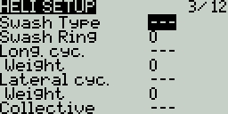
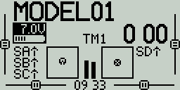
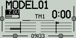
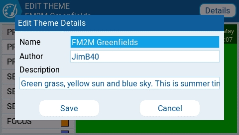
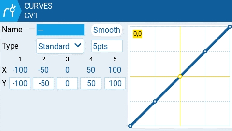

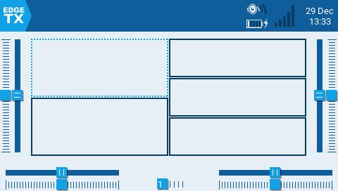
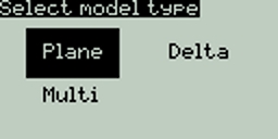
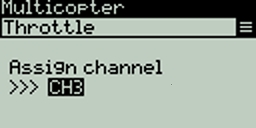
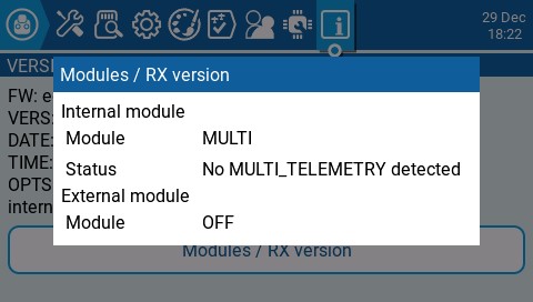
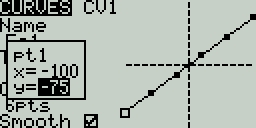
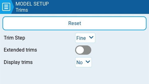
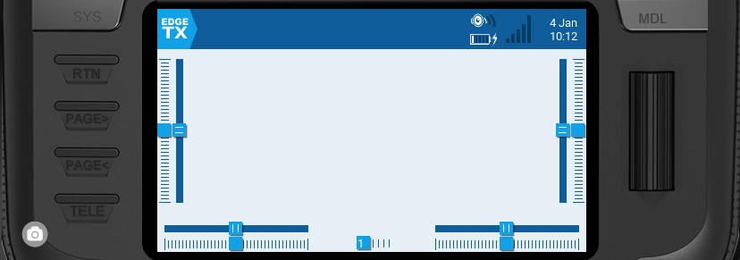
Receiver link quality (valid packets)
Receiver
RSNR
Receiver signal-to-noise ratio
Receiver
RFMD
Receiver packet rate
Receiver
TPWR
Transmitter transmitting power
Transmitter
TRSS
Transmitter signal strength antenna
Transmitter
TQly
Transmitter link quality (valid packets)
Transmitter
TSNR
Transmitter signal-to-noise ratio
Transmitter
ANT
Sensor for debugging only
Transmitter
GPS
GPS Coordinates
GPS / Flight Controller
Alt
GPS Altitudes
GPS / Flight Controller
Sats
GPS Satellites acquired
GPS / Flight Controller
Hdg
Magnetic orientation
GPS / Flight Controller
RXBt
Battery voltage
Flight Controller
Curr
Current draw
Flight Controller
Capa
Current consumption
Flight Controller
Ptch
FC Pitch angle
Flight Controller
Roll
FC Roll angle
Flight Controller
Yaw
FC Yaw angle
Flight Controller
FM
Flight mode
Flight Controller
VSPD
Vertical Speed
Flight Controller w/ Baro
1RSS
Received signal strength antenna 1 (RSSI)
Receiver
2RSS
Received signal strength antenna 2 (RSSI)
Receiver
Rqly
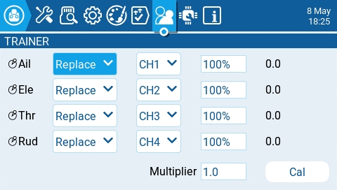
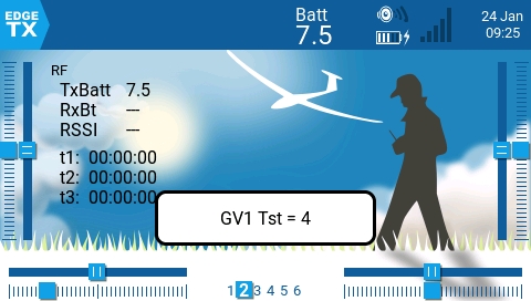
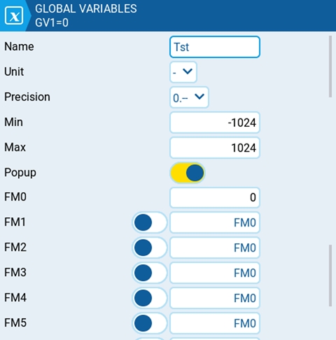
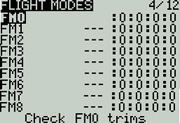
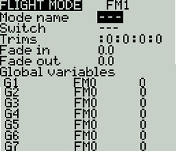
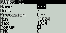
If using the radio in gamepad mode, both internal and external RF modules should be turned off. This will result in increased performance when connected to a computer via USB.
Off - RF Module is not used
PPM - Pulse position modulation, used by many generic JR compatible modules.
Telemetry - No telemetry or MLink
Channel Range - Channels that will be used.
PPM Frame – Frame length, pulse length, and polarity of the PPM frame. The frame length is automatically adjusted to the correct value when the number of transmitted channels is changed. However, this automatically assigned value can be manual changed.
XJT -
Protocol- D16, B8, LR2
Channel Range - Channels that will be used.
Failsafe Mode
DSM2
Protocol - LP45, DSM2, DSMX
Channel Range - Channels that will be used.
Receiver Number
CRSF
Baud Rate - the speed to which the Transmitter module and the Radio Handset communicate.
Status - Shows the packet radio configured on the trasmitter module.
Multi - Multiprotocol Module. The configuration options are unique to each selected protocol Configuration options for the multi-protocol module are described here:
R9M
Mode- FCC, EU, 868MHz, 915 MHZ
Failsafe Mode - The receiver will use this setting when the transmitter signal is not being received (signal loss).
R9M Access Note: In order for the mode R9M ACCESS to be visible in the mode dropdown, the AUX1 or AUX2 serial port must be configured to External Module on the page.
Channel Range - Channels that will be used.
Failsafe Mode - The receiver will use this setting when the transmitter signal is not being received (signal loss).
GHST - ImmersionRC Ghost
Channel Range - Channels that will be used.
Raw 12 bits - enable 12bit mode
SBUS
Channel Range - Channels that will be used.
Refresh Rate - Rate of refresh in milliseconds
FLYSKY
Protocol - AFHDS3, AFHDS2A
Module Status - Status of the module
Type -
LemonRx DSMP
Channel Range - Channels that will be used.
Bind - This puts the transmitter into bind mode. When in this mode the transmitter will make a chirp sound every 2.5 seconds.
All special functions have the configuration options below. Additional options may be added based on the selected function. See the Functions section below for these additional options.
Trigger - The switch or trigger that will make the special function active. Long pressing on this section will allow you to quickly select the category of the switch and filter the results. You can select the following filters: Switches, Trims, Logical Switches, Other and Invert
Function - The function that will be used. See below for function descriptions.
Enable - Toggle on/off to enable the function. To be able to activate the special function by a switch, it must be enabled. This option is usually the last option listed as a checkbox on the far right of the screen. Disabled special functions will not function regardless of the configured switch position.
Below are all the available functions in EdgeTX, what they do, as well as what additional configuration options that will be shown when the function is selected.
Adjust (Adjust Global Variable) - Changes the value of the specified global variable.
Global var - Select the global variable that you want to adjust.
Mode - Select the mode to change the global variable. Options are: Constant, Mixer Source, Global var, Inc/Decrement. Long-press the [Enter] button to select the mode.
Constant - Sets the specified global variable to the defined constant value.
Mixer Source - Sets the specified global variable to the defined mixer source value.
Global Var - Sets the specified global variable to the defined global variable value.
Inc/Decrement - Increments/decrements the specified global variable by the specified amount.
Audio Amp Off (select radios) - Disables the Audio Amplifier so that no sound comes from the speaker, including annoying feedback or interferance. This option is only available on select radios.
Backlight - adjusts the screen contrast (LED screens) or OLED brightness (OLED screens) based on the source defined in the value dropdown.
BgMusic - Plays the .wav file selected in the value field on a loop when enabled. The file shall be in the SOUNDS/(language)/ folder on the SD card.
BgMusic II - Temporarily pauses the .wav file playback specified in the BgMusic
Haptic - Causes the radio to vibrate (haptic feedback) when enabled.
Value - Type of vibration pattern. Options are: 0 - 3.
Repeat - Frequency to repeat the vibration pattern. Options are !- (do not vibrate at startup even if the switch is active), - (vibrate once), 1 thru 60 (vibrate every xx seconds).
Inst. Trim (Instant Trim) - Sets all trims to the current values of their respective sticks.
Lua (Lua Script) - Executes the Lua script defined in the value field. The Lua script must be located in /SCRIPTS/FUNCTIONS/ folder on the SD card. Lua scripts that display information on the screen cannot be executed with this special function.
Value - LUA script file to play from the SD card.
Repeat - Frequency to repeat the Lua script. Options are: ON (repeat indefinitely as long as switch is active) or 1x (once)
Overr.= (Channel Override) - Overrides the defined channel with the defined value.
CH - Channel to be overridden
Value - Value to replace the normal channel value. (Range -100 to +100)
Play Sound - Plays the sound selected in the value field when activated.
Value - Sound to play. Possible values are Beep1/2/3, Warn1/2, Cheep, Ratata, Tick, Siren, Ring, SciFi, Robot, Chirp, Tada, Crickt, AlmClk. Note: SD card sound pack is not required.
Repeat - Frequency to repeat the sound. Options are !- (do not play at startup even if the switch is active), - (play once), 1 thru 60 (play every xx seconds).
Play Track - Plays the .wav sound file selected in the value field when activated.
Value - .wav sound file to play from the SD card.
Repeat - Frequency to repeat the track. Options are !- (do not play at startup even if the switch is active), - (play once), 1 thru 60 (play every xx seconds).
Play Val - Announces the value of the selected element in the value field.
Value - The source for the value to announce. It can be an input, stick, pot, slider, trim, physical and logical switch, trainer import channel value, global variable, telemetry sensor or channel.
Repeat - Frequency to repeat the announcement. Options are !- (do not announce at startup even if the switch is active), - (announce once), 1 thru 60 (announce every xx seconds).
Push CS - (Push Customizable Switch) (select radios) - Presses the designated switch for the designated period of time.
Switch - Which customizable switch to press
Time - How long to press the customizable switch for. Options are 0.0 to 25.5 seconds. Input to the button will be ignored while this time is being served, allowing this to automate a press of the button, and block input (and retrigger of the function) until the time has elapsed.
RacingMode - Enables racing mode (low latency) for FrSky Archer RS receivers. Racing mode must also be enabled in External RF Module Settings.
Reset (Reset Timer)- Resets the timer or telemetry specified in the value back to their initial values.
Reset - Options are Tmr 1, Tmr 2, Tmr 3, All, and Telemetry. See Reset Telemetry for more information on what data is reset for each option.
RGB Led (select radios) - Run the selected LED related Lua script to animate RGB leds on the handset.
Value - LUA script file to play from the SD card (in the /SCRIPTS/RGBLED folder).
Repeat - Frequency to repeat the Lua script. Options are: ON (repeat indefinitely as long as switch is active) or 1x (once).
Screenshot - Creates screenshot as a .bmp file in the SCREENSHOT folder on the SD Card.
SD Logs - Creates a log .csv file of the radio and telemetry values in the LOGS folder on the SD Card. The radio will create a new entry into the log file based on the frequency configured in the Value setting. The value options are 0.0s - 25.5s (Note: 0.0 effectively disables this option). Each time the function is activated, the radio will create a new log file provided that the function is activated at least as long as the value setting. Note: Logging will not start if SD card has less than 50mb of free space.
Set (Set Timer) - Sets the specified timer to the specified value.
Timer - Options are Tmr 1, Tmr 2, Tmr 3
Value - The range is 00:00:00 to 08:59:59
SetFailsafe - Sets the custom failsafe values for the configured RF module (Internal/External) to the current stick position when activated. For this option to work, the Failsafe mode for the RF module must be set to custom.
Set Screen - Sets the telemetry screen or return to main view screen.
Value - 0 - 4. When set to 0, the normal main view will be loaded. When set to 1 - 4, the corresponding telemetry screen will be shown (if configured).
Repeat - Options are !- (do not trigger at startup even if the switch is active) and - (trigger once).
Trainer - Enables trainer mode.
Value - Specifies which controls will be given over to the student. Options include Axis (all sticks/primary inputs), Rud (Rudder), Ele (Elevator), Thr (Throttle), Ail (Aileron), and Chans (all channels).
Vario - Enables the variometer beeping sound for the ascent and descent of the model.
Volume - Changes the radio volume. The change source is specified in the Volume dropdown.
Pressing the [PAGE>] button will take you to the Telemetry screen.
Paste - Pastes a copied logical switch onto the selected logical switch. Note: it will overwrite the selected logical switch.
Clear - Deletes all configuration options for the selected logical switch.
After selecting to edit a logical switch, you will have the following configuration options:
Func - The logical function that you want to use. See Logical Switch Functions below for a description of the possible functions you can use.
V1 - The first variable in the expression to evaluate.
V2 -The second variable in the expression to evaluate.
AND switch - Switch that must be active to allow the logical switch to be evaluated for activation.
Duration - The duration that the logical switch will remain active (true) once meeting activation criteria.
Delay - Delay between when the activation criteria for the logical switch has been met and when the logical switch changes to the activated state (true).
Persist. (Sticky Switch only) - Preserves the value of the sticky switch when turning the radio off, or changing models, and restores the saved value on power on or selecting the model again.
In the expression, a and b represent sources (sticks, switches, etc.), and x represents the constants (values) to be compared.
a=x
True when the source V1 is exactly the same as the constant V2.
a~x
True when the source V1 is about the same as the constant V2.
a>x
True when the source V1 is greater than the constant V2.
a<x
True when the source V1 is less than the constant V2.
|a|>x
True when the absolute value of the source V1 is greater than the constant V2.
Pressing the [PAGE>] button will take you to the Special Functions screen.
The ADC filter is a filter for the proportional channels (sticks, pots, sliders), smoothing out smaller fast movements that occur due to noise in the system electronics. Normally, this filter should be disabled for models with flight controllers.
Mute if no sound: - When enabled, puts the transmitter in mute mode until a sound needs to be played. This prevents interference noise from high-powered TX modules from coming out of the transmitter speakers.
Select the module type for the internal module bay. Options are: Multi, XJT, ISRM, CRSF. When CRSF is selected, you can also select the baud rate. You can read more about baud rates here.
Options are Normal and OneBit. The default setting of Normal should be used by most users. Only users of X9D+ and X7 radios may want to use OneBit mode.
Mode - mode that the bluetooth module will be used in. The options are:
--- - Off
Telemetry - used for sending telemtry data over bluetooth.
Trainer - used for bluetooth trainer mode
Name - the name the bluetooth device will be seen as.
Settings Cog Icon - when selected will show you:
PIN Code - PIN code for bluetooth device in the radio (visible in Telemetry mode only)
Local addr - Identifying address of the bluetooth device in the radio.
Dist addr - Identifying address of bluetooth device that radio is connected to.
Displays a list of available auxiliary serial ports that can be configured and used. The listed ports are based on the ports that are available in the particular radio hardware. The ports listed below are for example only and may not be present in your radio.
AUX1 - First available auxiliary serial port can be configured with the below options:
OFF - Turned off.
Telem Mirror - The same telemetry data that goes to the external module bay is sent to the serial port.
Telemetry In - Receive telemetry data over the serial port.
SBUS Trainer - Connect the Instructor and Student radios over the serial port.
LUA - Send/receive data to/from Lua script.
GPS - Receive GPS telemetry data over the serial port.
CLI - Send commands to the radio via the command line.
External Module - This allows configuring the external access mod on runtime rather than by compilation option. First, configure the hardware port (only available on AUX1 as AUX2 has no TX DMA)
Then the module can be chosen:
AUX2 - Second available auxiliary serial port (depending on hardware), which has the same options as AUX1, except for External Module
USB-VCP - Virtual COM Port. This is one of the options presented when connecting your radio to the PC with most radios. Is often set to 'CLI' for radios with internal ExpressLRS RF modules in order to do firmware updates.
Port Power - Enables or disables the power output on the power supply pins next to serial ports that are available on some radios (presently only TX16S has this feature).
Calibration - For calibrating your physical radio controls (sticks, pots, sliders & 6-position switch). The radio will prompt you through the calibration steps.
Selecting one of the Axis, Pots, or Switches buttons will open the configuration screen. On these screens, you will see all the physical radio controls pre-defined by EdgeTX. Here you can add a 3 character label to the control as well as change the type of control as needed. Addionally, controls listed under the Pots screen can also be configured to be inverted.
The debug section allows for testing and debugging of the analog controls and keys.
Analogs - These screens will show you the data for your analog controls (Sticks, Sliders, Pots, 6-position switch) and the touch screen on your radio. There are four views - Calibrated analog, Filtered Raw Analog with deviation, Unfiltered raw analog, and Min Max and range.
Keys - This screen will show you the digital data for your keys, switches, trims, and the rotary encoder (roller).
The Inputs section is also commonly referred to as "Dual Rates" as it was previously called this in earlier versions of OpenTX.
The inputs screen shows you an overview of your configured inputs. Each row represents an input line and displays the following information from left to right: Input name, weight, activation switch, line name. These items are described in the Input configuration page area below.
Selecting an existing input line and pressing [Enter] will toggle between Copy/Paste mode and Move mode. In Copy/Paste mode, a copy of the input line is made which can be pasted in the desired input line. In Move mode, the selected input can be moved to a different line. Press the [Return] button to exit this mode.
Selecting an empty input line and pressing [Enter] will create a new input and open the input configuration page.
Selecting an existing input line and long-pressing [Enter] will give you the following options:
Edit - opens the input configuration page for that input line.
Insert before - Inserts a new input line before the selected input.
Insert after- Inserts a new input line after the selected input.
Copy - copies the selected input line.
Move - selects the input line to be moved. The input is moved using one of the paste commands after a new line is selected (i.e. cut & paste).
Delete - deletes the selected input line.
Paste before - pastes the copied or moved input line before the selected input line.
Paste after - pastes the copied or moved input line before the selected input line.
The input configuration page allows you to edit the input configuration parameters. To the right of the configuration parameters, you can see a live graph that shows how your configuration options will affect the slope of the input.
Input Name - Name for the input. Three characters are possible.
Line Name - Name of the individual line in the input. Multiple physical inputs can be mapped to one input by adding an additional input line under the input.
Source - The physical control used for the input. In addition to physical controls, you can also specify MAX (always returns 100), MIN (always returns -100), cyclic, trim switches, channel values, global variables and more. Moving the physical control after the source has been selected will automatically map it to that input. Long press [Enter] to bring up the list of available source categories.
Weight - Percentage value of the stick travel to use (often referred to as "rates"). You can also long press [Enter] to bring up a menu that will let you change this to be based on another input, axis, pot, MAX (always returns 100), MIN (always returns -100), cyclic, trim switches, channel values, global variables and more.
Offset - The value added to or subtracted from the input source. You can also long press [Enter] to bring up a menu that will let you change this to be based on another input, axis, pot, MAX (always returns 100), MIN (always returns -100), cyclic, trim switches, channel values, global variables and more.
Curve - Specifies the type of curve that will be used. The following curve options exist:
Diff - Multiplies only the range above or below the middle (0) by the specified %. Long press [Enter] to select the value to be sourced from another input, axis GV, etc.
Expo -The input value is changed exponentially. Increasing the % will result in a gentle slope near the middle(0). Decreasing the % will result in a steep slope near the middle (0). With a % of 0, the slope will be linear. Long press [Enter] to select the value to be sourced from another input, axis GV, etc.
Func -
Cstm - assigns a custom-defined curve. See for more information about custom-defined curves.
Modes - Specifies which flight modes this input is active for.
Switch - The switch that activates the input line. If no switches are defined, then it is always active.
Side - Specifies the input range for which this line setting is valid. If you select ---, it will be valid in the entire range of Source values. If you select x>0, it will be valid in the upper half of the value of Source. If you select x<0, it will be valid in the lower half of the value of Source.
Trim - Specifies whether or not to include the trim values in this input. Additionally, you can select a different trim to use for this input.
Pressing the [PAGE>] button will take you to the Mixes screen.
|X|
The range above the middle (0), the reaction is linear. The sign is inverted in the range below the middle (0). The curve draws a V-shaped graph.
f>0
The range above the middle (0) is always +100. The range below the middle (0) is always 0. The output value will always be either 0 or +100.
f<0
The range above the middle (0) is always 0. The range below the middle (0) is always -100. The output value will always be either 0 or -100.
|f|
The range above the middle (0) is always +100. The range below the middle (0) is always -100. The output value will always be either +100 or -100.


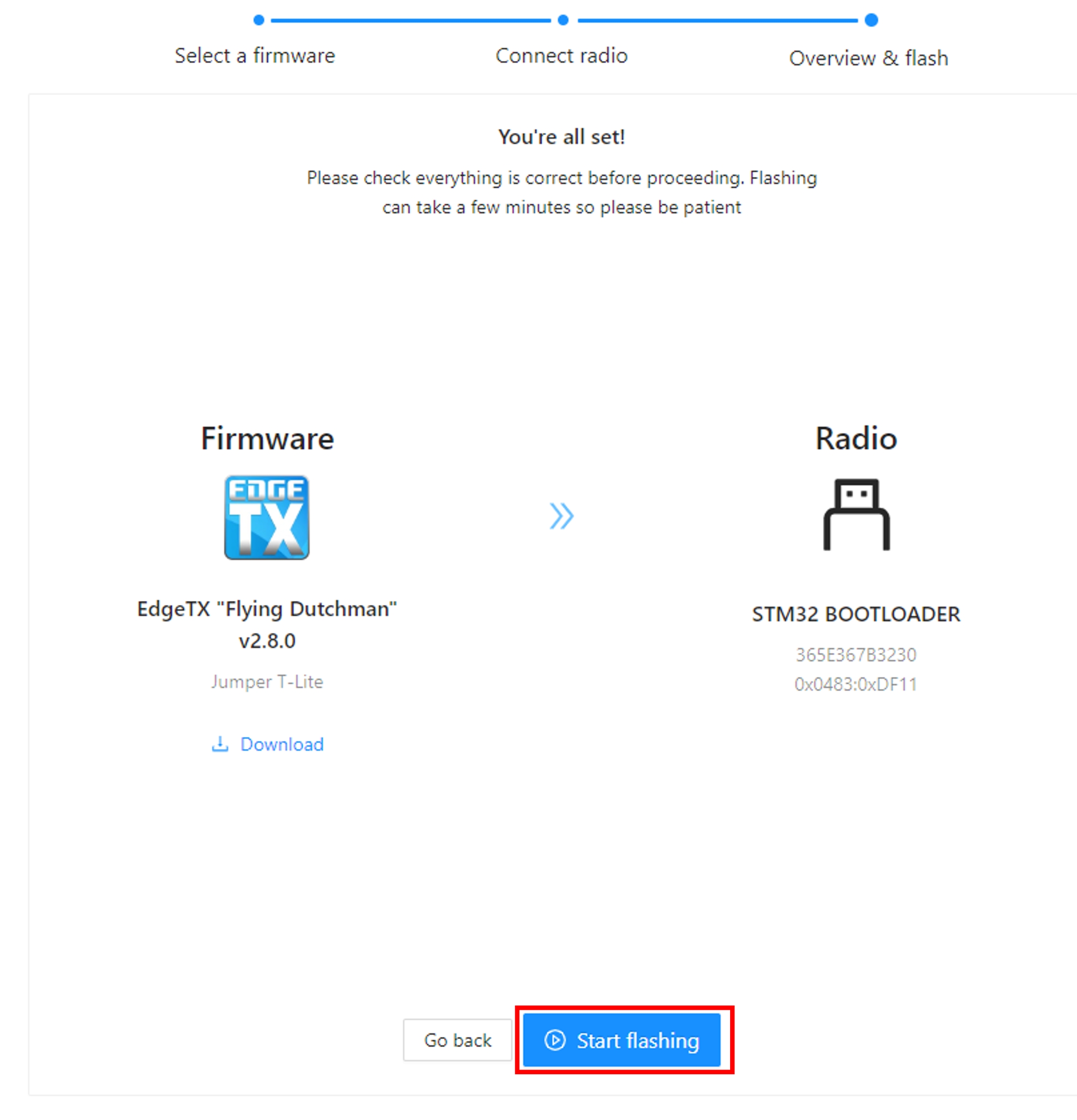
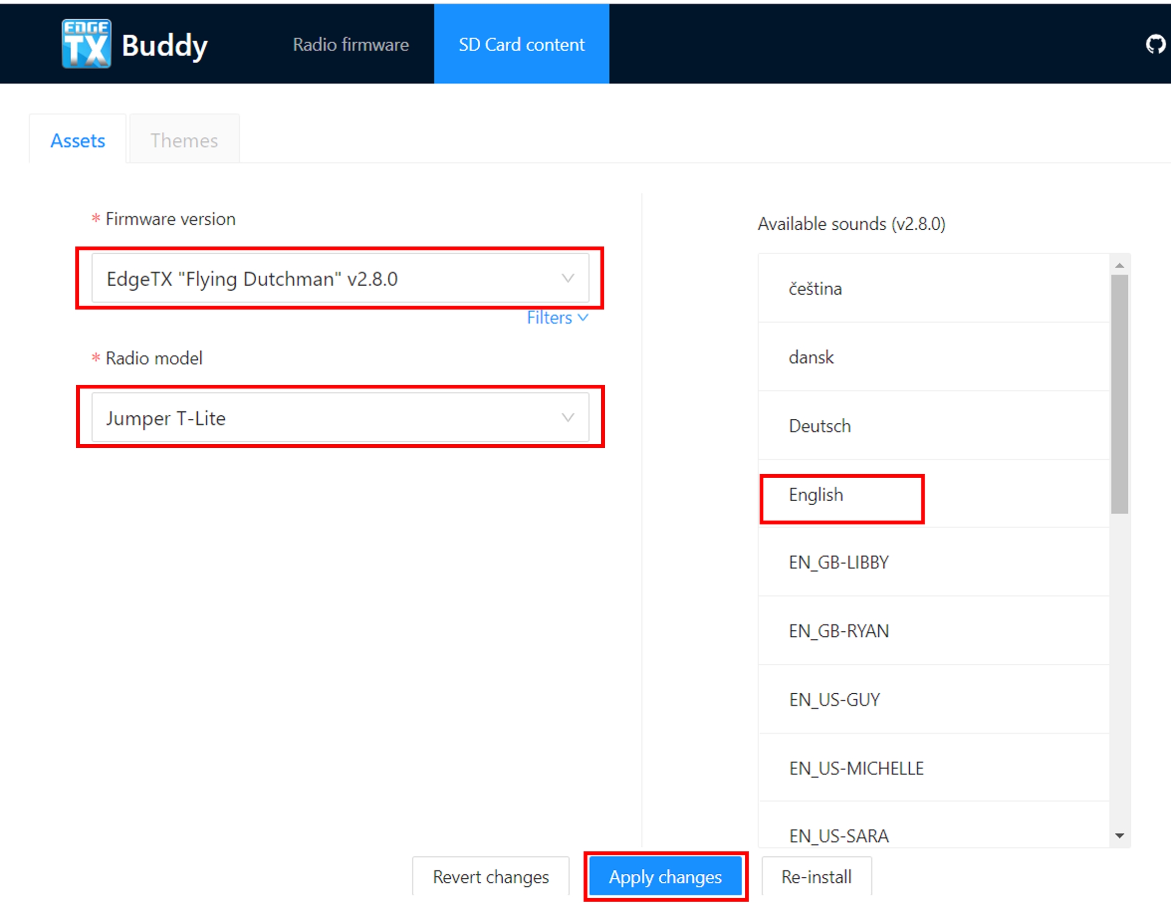
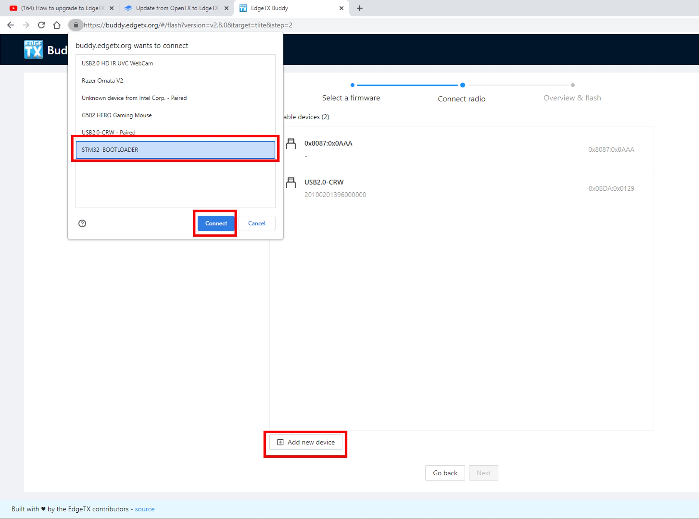
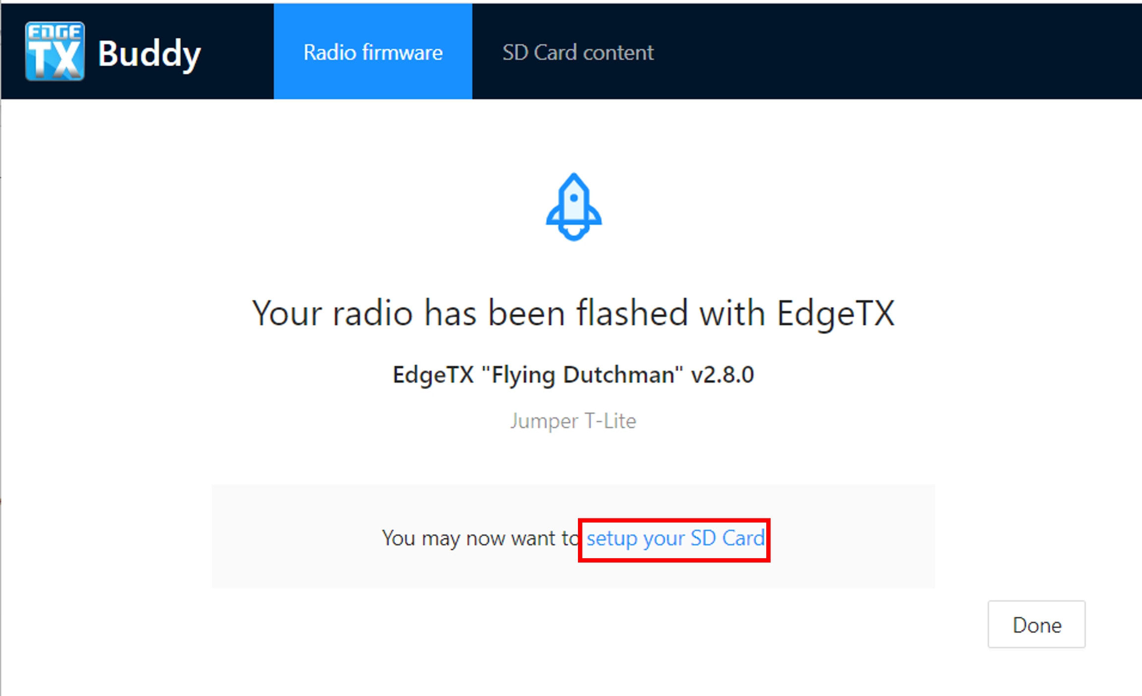
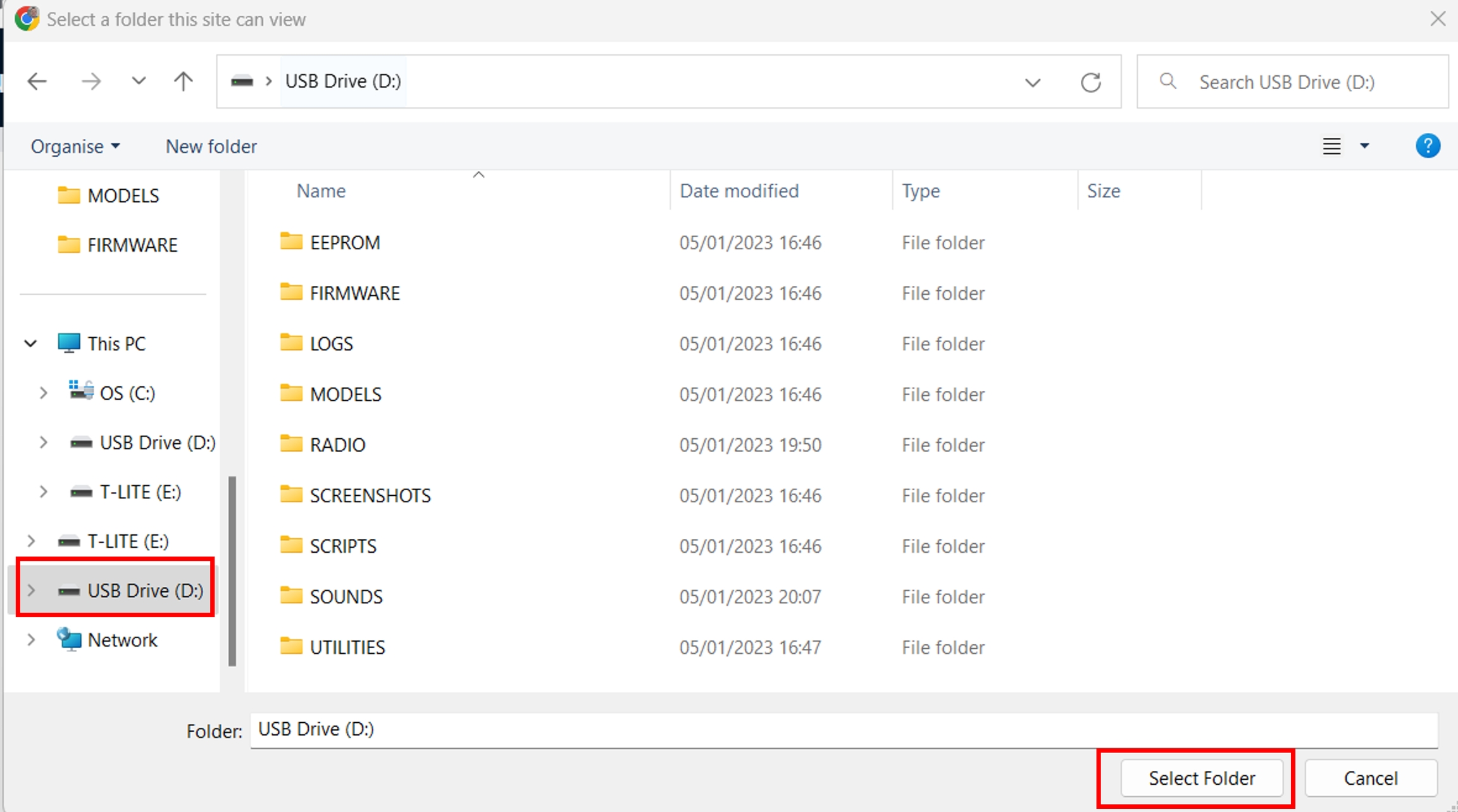
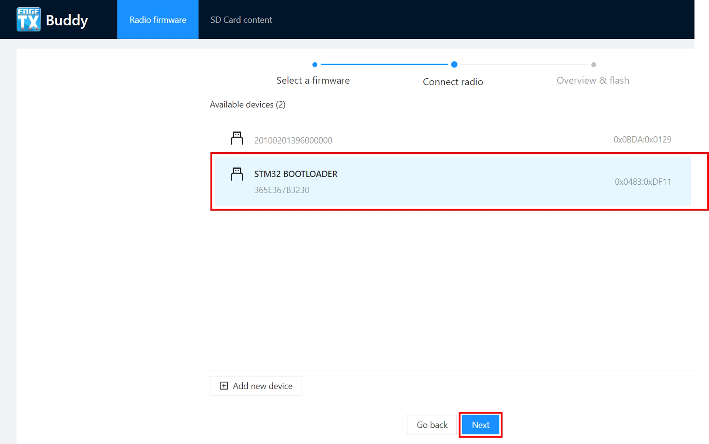
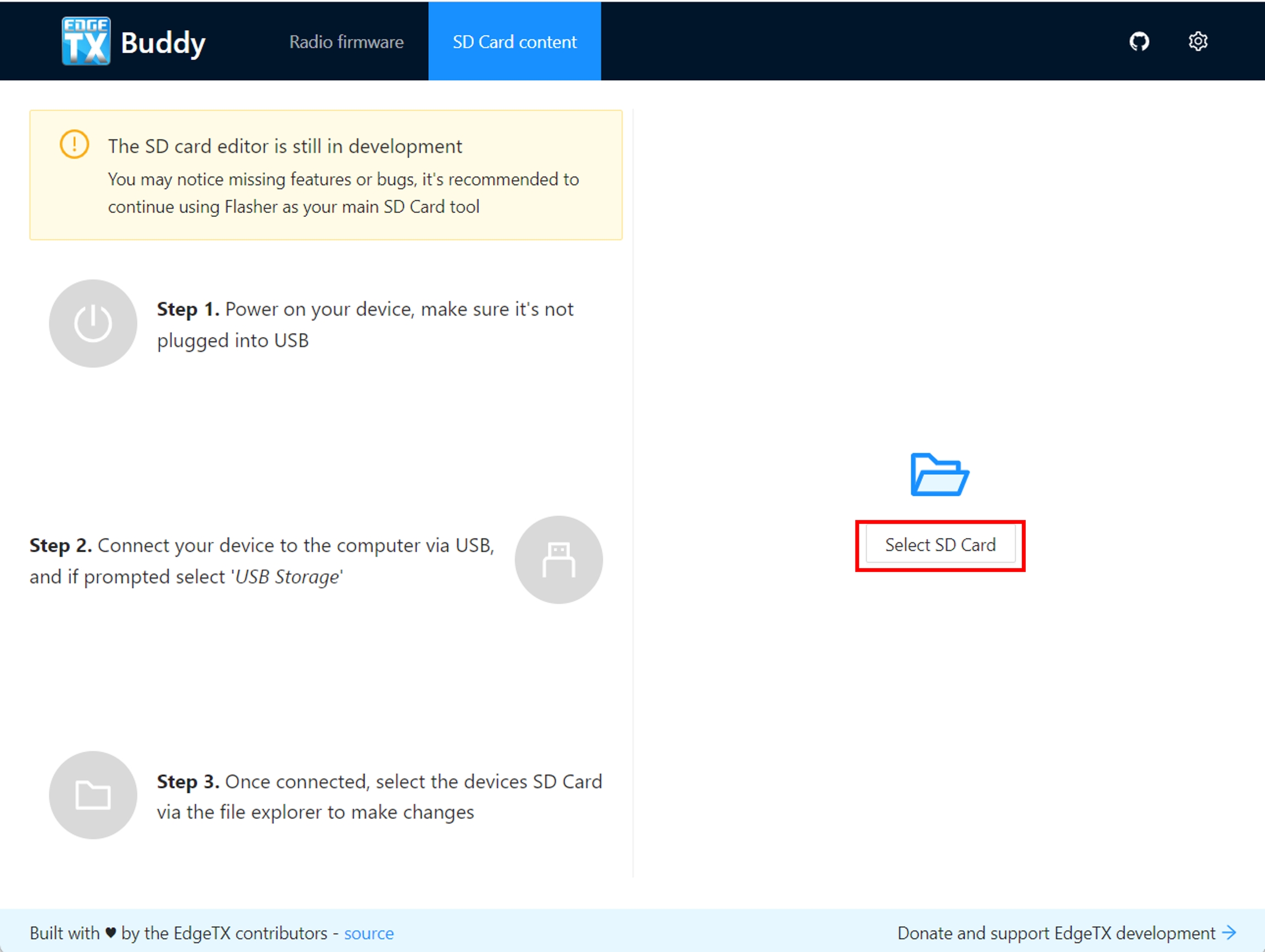
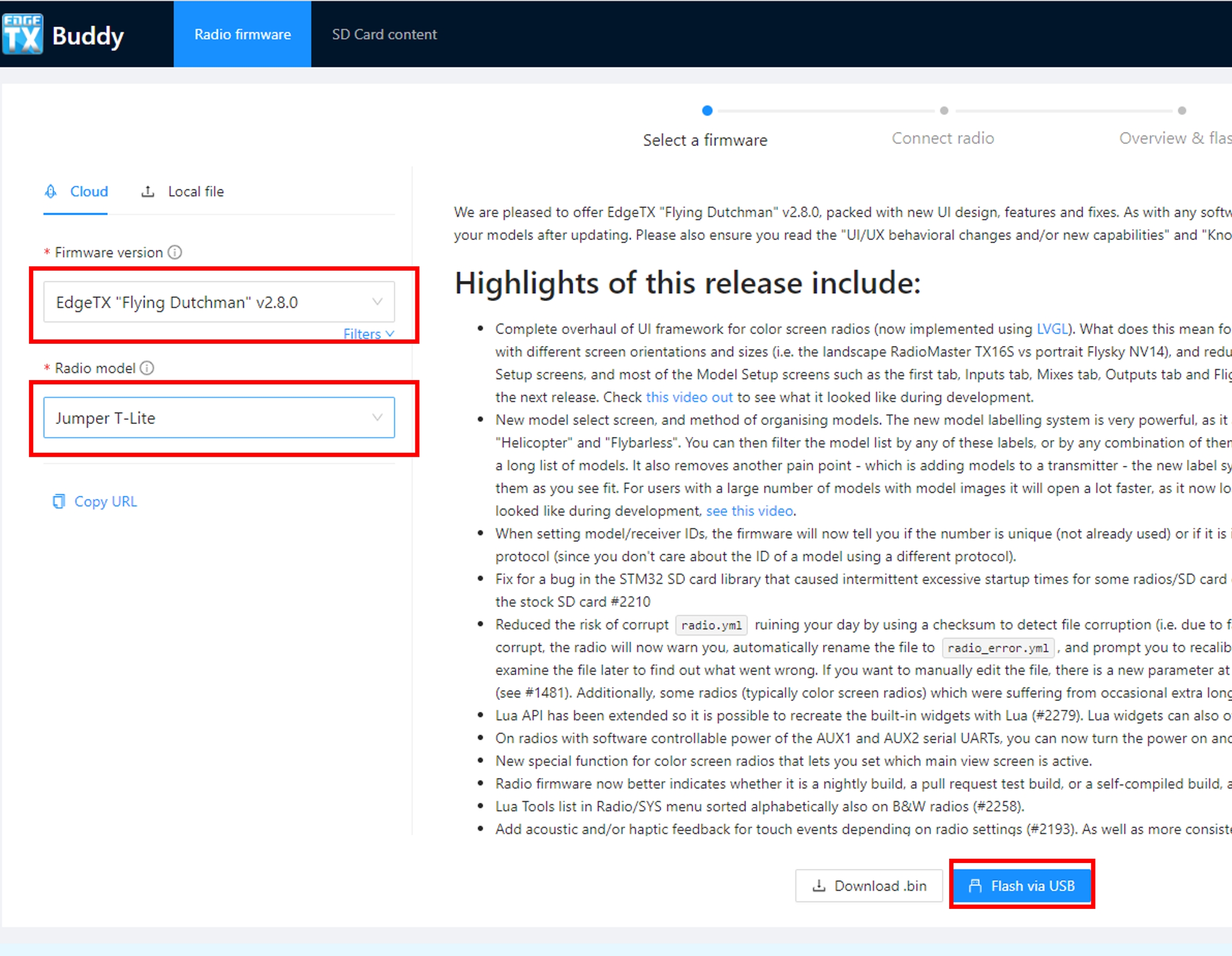
The Special Functions section of Model Setup, as the name implies, is where you can configure the special functions that are included in EdgeTX. These special functions add additional functionality beyond normal model controls such as enabling trainer mode, playing a sound, adjusting the radio backlight, adjusting radio volume, etc. On the special functions screen you will see all configured special functions as well as some of the configured options such as function name, activation switch, if the function is enabled, and other configuration options.
Selecting the + button will allow you to select an unused special function to configure and the special function configuration window will appear. See configuring special functions below for information about configuring new special functions.
Selecting an already configured special function will give you the following options:
Edit - Opens the special function configuration page
Copy - Copies the selected special function
Paste - Pastes a copied special function to the selected special function. Note: this will overwrite the value of the selected special function with the copied special function.
Insert - Inserts a blank special function above the selected special function
Clear - Clears all configured options from the selected special function.
Delete - Deletes the selected special function.
Enable - Enables special function
Disable - Disables special function
All special functions have the configuration options below. Additional options may be added based on the selected function. See the Functions section below for these additional options.
Trigger- The switch that will make the special function active.
Function - The function that will be used. See below for function descriptions.
Enable - Toggle on / off to enable the function. To be able to activate the special function by a switch, it must be enabled. Disabled special functions will not function regardless of the configured switch position.
Below are all the available functions in EdgeTX, what they do, as well as what other configuration options exist specifically for that function.
Adjust (Adjust Global Variable) - Changes the value of the specified global variable.
Global var - Select the global variable that you want to adjust.
Mode - Select the mode to change the global variable. Options are: Constant, Mixer Source, Global var, Inc/Decrement
Constant - Sets the specified global variable to the defined constant value.
Audio Amp Off (select radios) - Disables the Audio Amplifier so that no sound comes from the speaker, including annoying feedback or interference.
Backlight - Adjusts the brightness of the radio screen based on the source defined in the value dropdown. Brightness is limited to the On / Off values configured in the Radio Setup -> Backlight Screen.
BgMusic - Plays the .wav file selected in the value field on a loop when enabled. The file shall be in the SOUNDS/(language)/ folder on the SD card.
BgMusic II - Temporarily pauses the .wav file playback specified in the BgMusic
Haptic - Causes the radio to vibrate (haptic feedback) when enabled.
Value - Type of vibration pattern. Options are: 0 - 4.
Repeat - Frequency to repeat the vibration pattern. Options are !1x (do not vibrate at startup even if the switch is active), 1x (vibrate once), 1s thru 60s (vibrate every xx seconds).
Inst. Trim (Instant Trim)- Sets all trims to the current values of their respective sticks.
Lua Script - Executes the Lua script defined in the value field. The Lua script must be located in /SCRIPTS/FUNCTIONS/ folder on the SD card. Lua scripts that display information on the screen cannot be executed with this special function.
Value - LUA script file to play from the SD card.
Repeat - Frequency to repeat the Lua script. Options are: ON (repeat indefinitely as long as switch is active) or 1x (once)
No Touch - Disables the touch interface for touchscreen-enabled radios.
Override (Channel Override) - Overrides the defined channel with the defined value.
CH - Channel to be overridden
Value - Value to replace the normal channel value. (Range -100 to +100)
Play Sound - Plays the sound selected in the value field when activated.
Value - Sound to play. Possible values are Beep1/2/3, Warn1/2, Cheep, Ratata, Tick, Siren, Ring, SciFi, Robot, Chirp, Tada, Crickt, AlmClk. Note: SD card sound pack is not required.
Repeat - Frequency to repeat the sound. Options are !1x (do not play at startup even if the switch is active), 1x (play once), 1s thru 60s (play every xx seconds).
Play Track - Plays the .wav sound file selected in the value field when activated.
Value - .wav sound file to play from the SD card.
Repeat - Frequency to repeat the track. Options are !1x (do not play at startup even if the switch is active), 1x (play once), 1s thru 60s (play every xx seconds).
Play Value - Announces the value of the selected element in the value field.
Value - The source for the value to announce. It can be an input, stick, pot, slider, trim, physical and logical switch, trainer import channel value, global variable, telemetry sensor or channel.
Repeat - Frequency to repeat the announcement. Options are !1x (do not announce at startup even if the switch is active), 1x (announce once), 1s thru 60s (announce every xx seconds).
RacingMode - Enables racing mode (low latency) for FrSky Archer RS receivers. Racing mode must also be enabled in External RF Module Settings.
Reset (Reset Timer)- Resets the timer or telemetry specified in the value back to their initial values.
Reset - Options are Timer 1, Timer 2, Timer 3, Flight, and Telemetry. See for more information on what data is reset for each option.
Screenshot - Creates screenshot as a .bmp file in the SCREENSHOT folder on the SD Card.
SD Logs - Creates a log .csv file of the radio and telemetry values in the LOGS folder on the SD Card. The radio will create a new entry into the log file based on the frequency configured in the Interval setting. The value options are 0.1s - 25.5s. Each time the function is activated the radio will create a new log file provided that the function is activated at least as long as the value setting. Note: Logging will not start if SD card has less than 50mb of free space.
Set (Set Timer) - Sets the specified timer to the specified value.
Timer - Options are Timer 1, Timer 2, Timer 3
Value - The range is 00:00:00 to 08:59:59
SetFailsafe - Sets the custom failsafe values for the selected module (Internal/External) to the current stick position when activated. For this option to work, the Failsafe mode for the RF module must be set to custom.
Set Main Screen - Changes the current visible screen to the screen number defined.
Value - The screen number as defined in the
Repeat - When the switch remains active, the repeat value determines how often the special function will change the screen to the defined screen. Options are !1x (do not change at startup even if the switch is active), 1x (change once), 1s thru 60s (change every xx seconds). This is useful because when the switch has been activated, the user can still manually switch screens, and then it will change back to the defined screen after the defined duration.
Trainer - Enables trainer mode.
Value - Specifies which controls will be given over to the student. Options include Axis (all sticks / primary controls), Rud (Rudder), Ele (Elevator), Thr (Throttle), Ail (Aileron), and Chans (all channels).
Vario - Enables the variometer beeping sound for the ascent and descent of the model.
Volume - Changes the radio volume. The change source is specified in the Volume dropdown.
The SD Card screen shows you the contents of your SD card, allows you to navigate the folders and interact with the files in the folders. All folders contain a README.txt file that describes what type of files belong in this folder. After selecting a file in one of the folders, you will be presented with some of the options below, depending on the file type that was selected:
Assign bitmap - Assigns the selected image file as the model image of the currently selected model (for 212x128 "widescreen" radios).
Copy - Copies the selected file.
Delete - Deletes the selected file.
Execute - Executes a Lua script. Used for files ending in .lua
Flash [target]- Flashes the selected firmware file to the select target module. Examples: Flash Bootloader, Flast Internal Multi.
Paste - Pastes the copied file.
Play - Plays the selected sound file.
Rename - Renames the file.
View text - Views the selected .txt, .csv, and .lua files.
The folders listed on the SD card screen are the same as what you will see when connecting your radio to your computer. Below are the folder names and explanations for all the folders that come with the default EdgeTX SD Card.
The backup folder contains model files for models that were backed up from the EEPROM. This folder will only be present on radios that store the model files in EEPROM.
Place the firmware files that you want to flash in this folder. This folder is empty by default (except for the readme.txt file). When selecting a .bin file you will be given the option to flash the firmware to a particular module. Also, only firmware files in this location will be visible from the bootloader menu.
NOTE: This folder is only used for radios with 212x64 displays.
Place your custom model image files in this folder. This folder is empty by default (except for the readme.txt file). Selecting an image file will give you the option to Assign Bitmap, which assigns the selected image file as the model image of the currently selected model.
The ideal image size for model images is 64x32 pixels. The picture format should be .bmp The image file name should not exceed 9 characters and the image formatting should be 4 bit indexed colored mode.
This is where the log files that are configured in the SD Logs are written. These files can be viewed with the View text option. This folder is empty by default (except for the readme.txt file).
This is where the model files, label information, and preflight checklists are stored. Each model will have a model[#].yml file that contains all configured options.
Models that are deleted via the radio will be moved to the DELETED folder that is included in this folder. The remaining model files are what will be visible on the Model Select screen.
If you have configured the Display checklist option in model settings, the model notes file goes in this folder. The model notes file must be a .txt file and must have the EXACT same name as the model it is for, for example: Mobula6.txt. The text in the file is up to the user.
This folder contains the radio.yml file. This file contains all the radio configuration data. If this file is corrupted or missing, the radio will go into Emergency Mode and will create a new radio.yml file with the default settings.
This is where the screenshot image files that are configured in the Screenshot are written. This folder is empty by default (except for the readme.txt file).
This folder and its subfolders are where the Lua scripts get placed. It contains the following sub-folders by default. You can download additional Lua scripts from .
Functions - This folder is where the functions Lua scripts that can be activated by the Lua Script must be placed. This folder is empty by default (except for the readme.txt file). More information about function Lua scripts can be found here: .
Mixes - This folder is where the Lua mixer scripts shall be placed. This folder is empty by default (except for the readme.txt file). More information about Mixer Lua scripts can be found here:
RGBLED - This folder is where Lua scripts that control the RGB Leds (if hardware available) are stored.
This folder is where the EdgeTX sound packs for your radio get placed. The sound packs are language-specific and correlate to the Voice language option in Radio Setup. Selecting a sound file from this folder will give you the option Play, which plays the selected sound file.
Sound packs are available for manual download at: . It is also possible to create custom sounds to use in EdgeTX. For your custom sounds to be playable by EdgeTX ensure that they meet the following criteria:
File Name: 123456.wav (up to 6 characters plus .wav)
Sample Rate: 32 kHz (or 16 Khz, 8Khz)
Bits / Sample: 16 (or 8)
Tracks: 1, mono
Pressing the [PAGE>] button will take you to the Radio Setup screen.
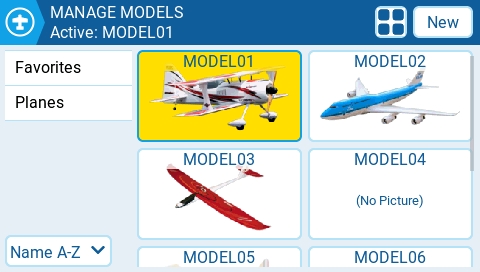
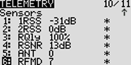
The SD Card screen shows you the contents of your SD card, allows you to navigate the folders and interact with the files in the folders. All folders contain a README.txt file that describes what type of files belong in this folder. After selecting a file in one of the folders, you will be presented with some of the options below, depending on the file type that was selected:
Assign bitmap - Assigns the selected image file as the model image of the currently selected model.
Copy - Copies the selected file.
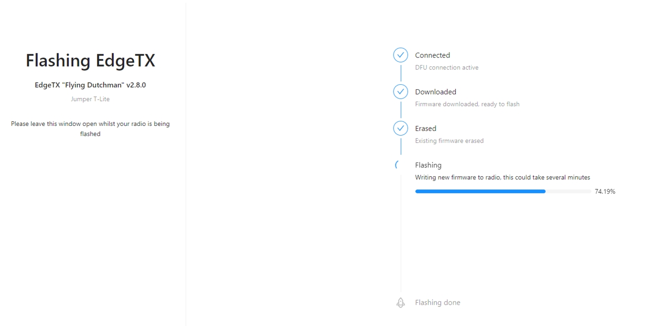
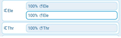
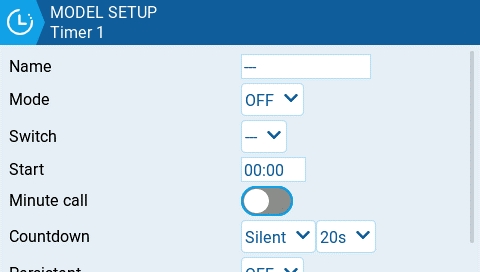
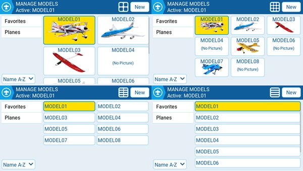
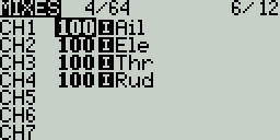
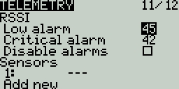
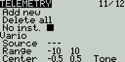

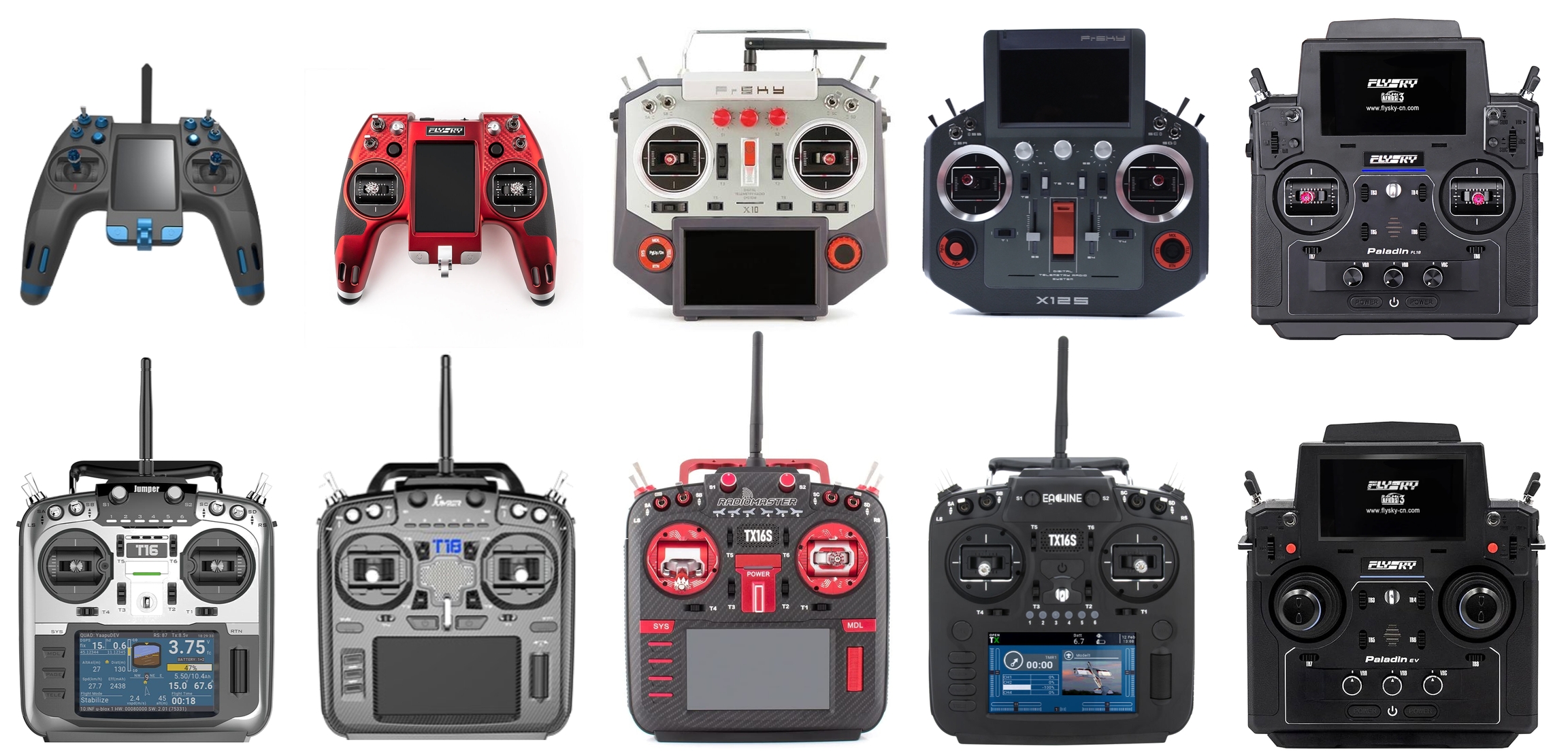
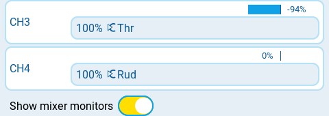
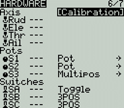
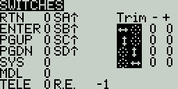
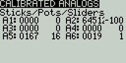
Not Set - failsafe mode is not set.
Hold – The receiver keeps channel values at their last received state from the transmitter.
No pulses – No PWM pulses are output.
Receiver – Follows the fail-safe settings configured on the receiver. Follow the instructions that come with the receiver.
Custom – The receiver changes the channel values to the custom set values.
Custom Set – Each channel can have its own setting. The options are a value, hold and no pulses.
Receiver Number - a user-assigned number for a model that is sent to the receiver when bound
Bind - This puts the transmitter into bind mode. When in this mode the transmitter will make a chirp sound every 2.5 seconds.
Range . This puts the transmitter into range check mode. When in this mode, the RSSI value is displayed and a sound is made every 5 seconds.
Bind - This puts the transmitter into bind mode. When in this mode the transmitter will make a chirp sound every 2.5 seconds.
Range . This puts the transmitter into range check mode. When in this mode, the RSSI value is displayed and a sound is made every 5 seconds.
Receiver Number - a user-assigned number for a model that is sent to the receiver when bound
Hold – The receiver keeps channel values at their last received state from the transmitter.
No pulses – No PWM pulses are output.
Receiver – Follows the fail-safe settings configured on the receiver. Follow the instructions that come with the receiver.
Custom – The receiver changes the channel values to the custom set values.
Custom Set – Each channel can have its own setting. The options are a value, hold and no pulses.
Receiver Number - a user-assigned number for a model that is sent to the receiver when bound
Bind - This puts the transmitter into bind mode. When in this mode the transmitter will make a chirp sound every 2.5 seconds.
Range . This puts the transmitter into range check mode. When in this mode, the RSSI value is displayed and a sound is made every 5 seconds.
RF Power - The output power for the transmitter module. The options change based on the selected mode.
Not Set - failsafe mode is not set.
Hold – The receiver keeps channel values at their last received state from the transmitter.
No pulses – No PWM pulses are output.
Receiver – Follows the fail-safe settings configured on the receiver. Follow the instructions that come with the receiver.
Custom – The receiver changes the channel values to the custom set values.
Custom Set – Each channel can have its own setting. The options are a value, hold and no pulses
Module - Please refer to FrSky documentation for these configuration settings
Register
Range
Options
Receiver No (Number) - a user-assigned number for a model that is sent to the receiver when bound
Bind - This puts the transmitter into bind mode. When in this mode the transmitter will make a chirp sound every 2.5 seconds.
Module Options- Please refer to FLYSKY documentation for these configuration settings
Channel Range - Channels that will be used.
Failsafe Mode - The receiver will use this setting when the transmitter signal is not being received (signal loss).
Not Set - failsafe mode is not set.
Hold – The receiver keeps channel values at their last received state from the transmitter.
No pulses – No PWM pulses are output.
Receiver – Follows the fail-safe settings configured on the receiver. Follow the instructions that come with the receiver.
Custom – The receiver changes the channel values to the custom set values.
Custom Set – Each channel can have its own setting. The options are a value, hold and no pulses.
Receiver (number) - a user-assigned number for a model that is sent to the receiver when bound
Bind - This puts the transmitter into bind mode. When in this mode the transmitter will make a chirp sound every 2.5 seconds.
|f|
The range above the middle (0) is always +100. The range below the middle (0) is always -100. The output value will always be either +100 or -100.
---
The slope will be linear.
X>0
The range below the middle (0) is always 0. Above the middle (0), the slope is linear.
X<0
The range above the middle (0) is always 0. Below the middle (0), the slope is linear.
|X|
The range above the middle (0), the reaction is linear. The sign is inverted in the range below the middle (0). The curve draws a V-shaped graph.
f>0
The range above the middle (0) is always +100. The range below the middle (0) is always 0. The output value will always be either 0 or +100.
f<0
The range above the middle (0) is always 0. The range below the middle (0) is always -100. The output value will always be either 0 or -100.
Global Var - Sets the specified global variable to the defined global variable value.
Inc/Decrement - Increments/decrements the specified global variable by the specified amount.
Tools - Contains the Lua scripts that are available in the Tools screen.
Wizards - Contains the Wizard Lua scripts that are available in the Tools screen.
Compression Codec: PCM
Delete - Deletes the selected file.
Execute - Executes a Lua script. Used for files ending in .lua
Flash [target]- Flashes the selected firmware file to the select target module. Examples: Flash Bootloader, Flast Internal Multi.
Paste - Pastes the copied file.
Play - Plays the selected sound file.
Rename - Renames the file.
View text - Views the selected .txt, .csv, and .lua files.
The folders listed on the SD card screen are the same as what you will see when connecting your radio to your computer. Below are the folder names and explanations for all the folders that come with the default EdgeTX SD Card.
Place the firmware files that you want to flash in this folder. This folder is empty by default (except for the readme.txt file). When selecting a .bin file you will be given the option to flash the firmware to a particular module. Also, only firmware files in this location will be visible from the bootloader menu. Selecting a .frsk file will give you the option to "Flash RX by int OTA".
Place your custom model or splash screen image files in this folder. This folder is empty by default (except for the readme.txt file). Selecting an image file will give you the option to Assign Bitmap, which assigns the selected image file as the model image of the currently selected model.
The ideal image size for model images used for thumbnails on the Model Manager screen is 156x92 pixels. If you plan to use the Model Info widget, you may want a increase the image size to 192x114 pixels for better visual quality at the increased size. For performance reasons, it is NOT recommeded to use a higher resolution image. The picture format should be .png. The image file name should not exceed 9 characters.
The ideal image size for Splash Screen images is the actual radio screen size (480x272 pixels for most color screen radios). The picture format should be .png. The image file name must be splash.png. Screen dimensions for the supported color screen radios can be found here.
Users can configure a custom image to be displayed during the radio shutdown by adding a custom shutdown.png to the IMAGES folder.
This is where the log files that are configured in the special function SD Logs are written. These files can be viewed with the View text option. This folder is empty by default (except for the readme.txt file).
This is where the model files, label information, and preflight checklists are stored. Each model will have a model[#].yml file that contains all configured options. Additionally, there is a labels.yml file that contains all the label information for your models.
Models that are deleted via the radio will be moved to the DELETED folder that is included in this folder. The remaining model files are what will be visible on the Model Select screen.
Any model files that are found in this folder that are not listed in the Models.yml file (if used) will be moved to the UNUSED folder.
If you have configured the Display checklist option in model settings, the model notes file goes in this folder. The model notes file must be a .txt file and must have the EXACT same name as the model it is for, for example: Mobula6.txt. The text in the file is up to the user.
This folder contains the radio.yml file. This file contains all the radio configuration data. If this file is corrupted or missing, the radio will go into Emergency Mode and will create a new radio.yml file with the default settings.
This is where the screenshot image files that are configured in the special function Screenshot are written. This folder is empty by default (except for the readme.txt file).
This folder and its subfolders are where the Lua scripts get placed. It contains the following sub-folders by default. You can download additional Lua scripts from https://github.com/EdgeTX/lua-scripts.
Functions - This folder is where the functions Lua scripts that can be activated by the special function Lua Script must be placed. This folder is empty by default (except for the readme.txt file). More information about function Lua scripts can be found here: Function Scripts.
Mixes - This folder is where the Lua mixer scripts shall be placed. This folder is empty by default (except for the readme.txt file). More information about Mixer Lua scripts can be found here: Custom Mixer Scripts
Tools - Contains the Lua scripts that are available in the screen.
Wizards - Contains the Wizard Lua scripts that are available in the screen.
This folder is where the EdgeTX sound packs for your radio get placed. The sound packs are language-specific and correlate to the Voice language option in Radio Setup. Selecting a sound file from this folder will give you the option Play, which plays the selected sound file.
Sound packs are available for manual download at: https://github.com/EdgeTX/edgetx-sdcard-sounds/releases. It is also possible to create custom sounds to use in EdgeTX. For your custom sounds to be playable by EdgeTX ensure that they meet the following criteria:
File Name: 123456.wav (up to 6 characters plus .wav)
Sample Rate: 32 kHz (or 16 Khz, 8Khz)
Bits / Sample: 16 (or 8)
Tracks: 1, mono
Compression Codec: PCM
This is where model template files are stored. By default, it will have the following sub-folders:
PERSONAL - If you save your models as templates, then they get stored here.
SoarETX - A collection of sailplane templates by: Jesper Frickmann
Wizard - Simple model templates that use the Lua Wizard scripts to configure the models.
This folder contains the theme packs for EdgeTX. The EdgeTX SD card comes with several theme packs automatically installed.
You can download and add additional themes from: https://github.com/EdgeTX/themes.
This is where the widget files are stored. You can add additional widgets to this folder to use with EdgeTX. For more information about the widgets that are pre-installed with EdgeTX, see Widgets. You can download additional widgets from https://github.com/EdgeTX/lua-scripts.
|a|<x
True when the absolute value of the source V1 is less than the constant V2.
AND
True when both sources V1 and V2 are TRUE.
OR
True when either source V1 or V2 is TRUE.
XOR
True when the source V1 and V2 positions do not match.
Edge
Momentarily true when the source V1 has been active for the defined period of time and then deactivated. The first time field (T1) under V1 is the minimum active duration required for source V1 to activate the logical switch. The second time (T2) is the maximum time allowed for the source V1 to be active for the logic switch to be activated. When T2 is set to --, the logical switch will be true regardless of how long V1 has been active. When T2 is set to 3, if V1 is active for more than 3 seconds, the logical switch will not be set to true when the source is deactivated. When T2 is set to <<, the logical switch will be true when the time conditions in T1 are met without source V1 being deactivated.
a=b
True when source V1 is the same as source V2.
a>b
True if source V1 is greater than source V2.
a<b
True if source V1 is less than source V2.
△>x
Momentarily true every time the source V1 changes by more than the amount indicated by the constant V2.
|△|>x
Momentarily true every time the absolute value of the source V1 changes by more than the amount indicated by the constant V2.
Tim (Timer)
Momentarily true every xxx seconds. Argument V1 is the duration that the logical switch is true (active). Argument V2 is the time between logical switch activations. Repeats timer cycle as long as the defined switch is active.
Stky (Sticky)
"Sticks" true after switch V1 is active (true) and stays active (true) regardless of V1 position until switch V2 is activated (true) and "unsticks" or deactivates (false) the logical switch. Has Persist. (Persistence) option that allows the value of the logical switch to be preserved across power cycles or when switching away from and back to the model.

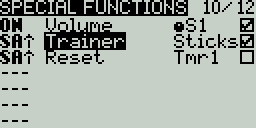
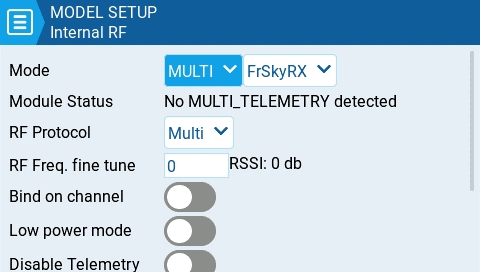
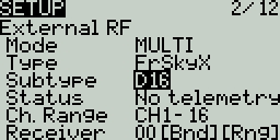
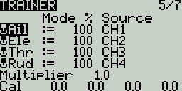

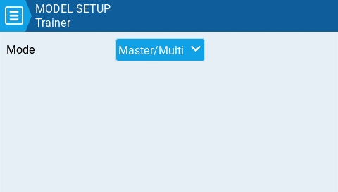
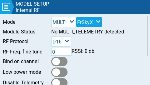
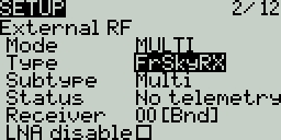
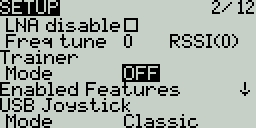
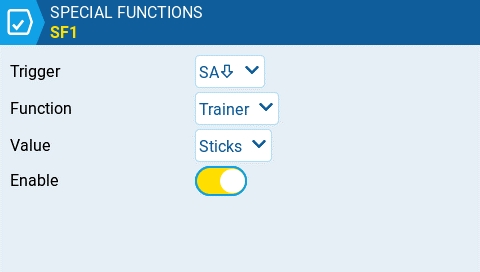
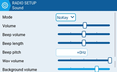
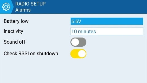
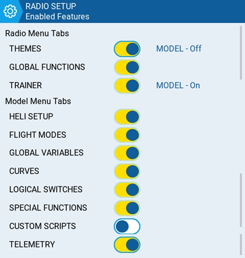
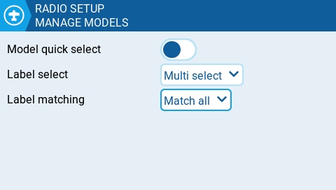
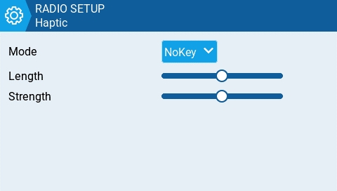
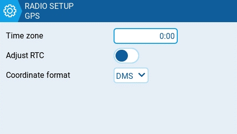
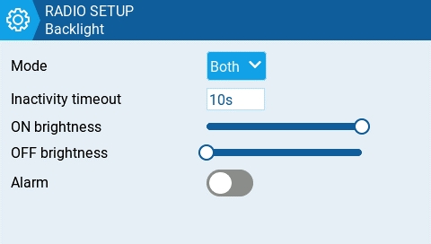
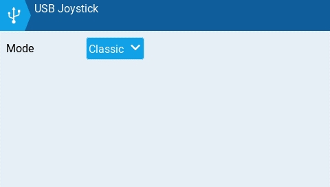
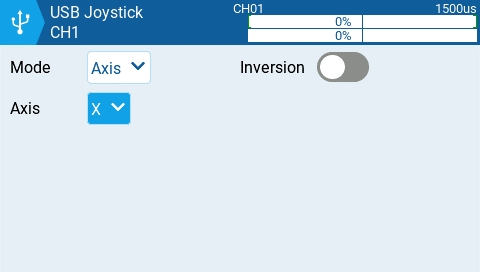

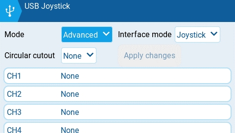

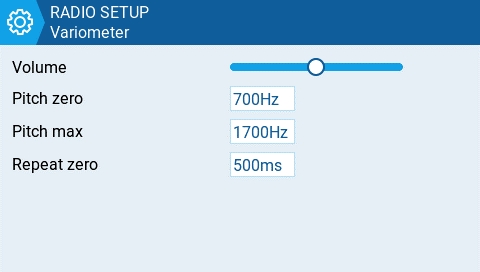
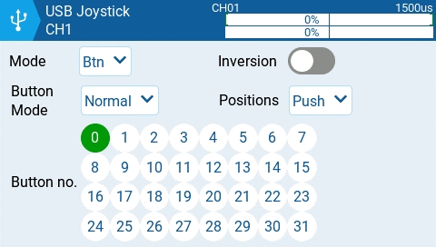
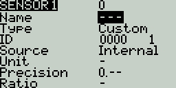
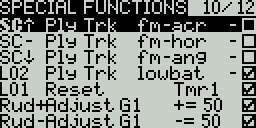
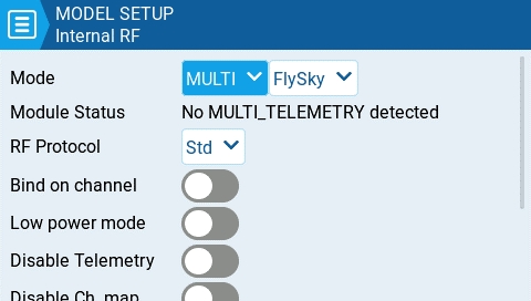
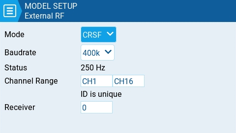

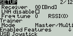
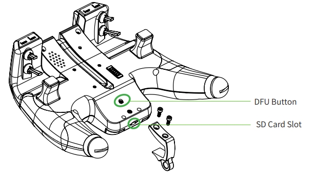
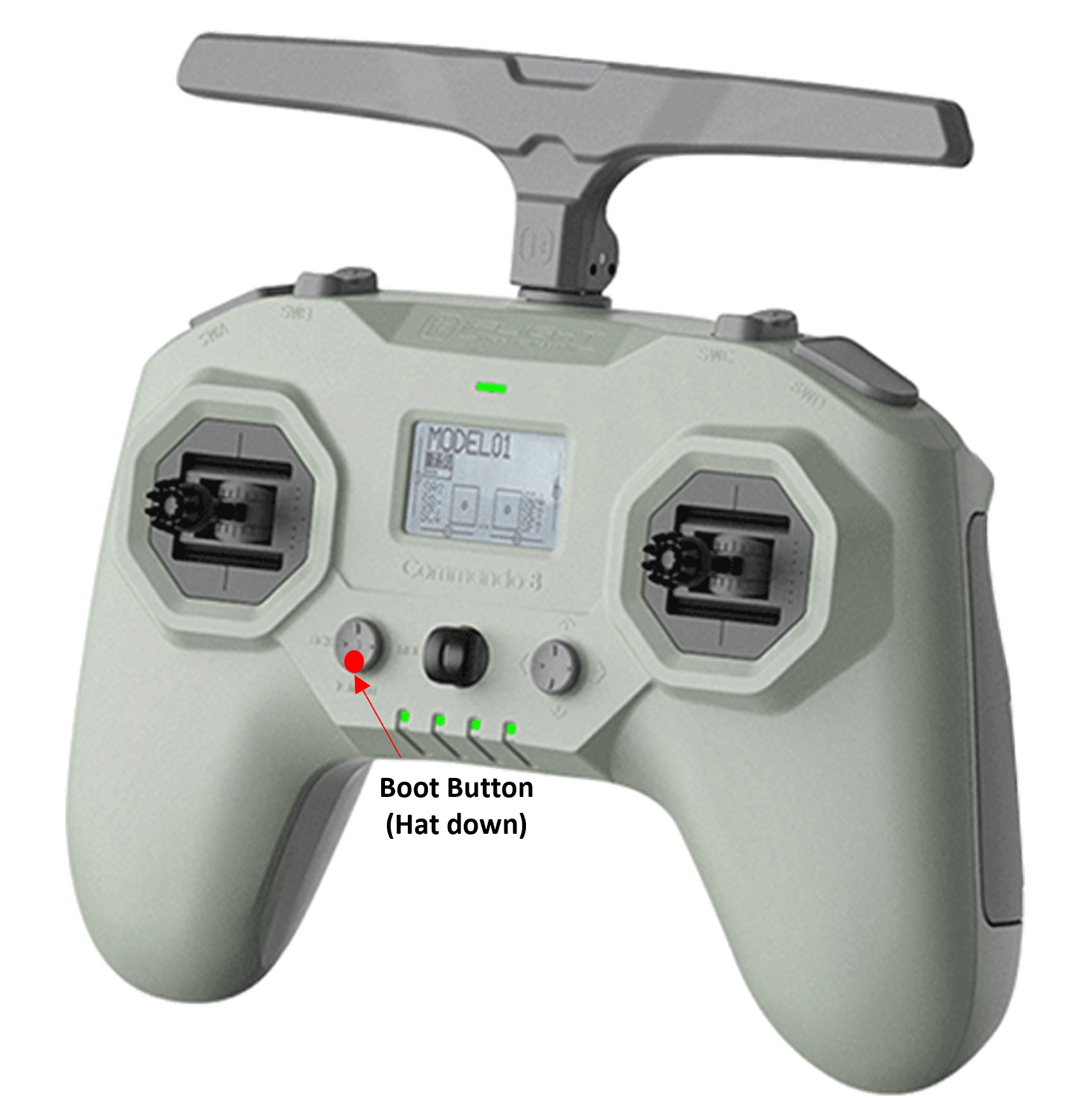
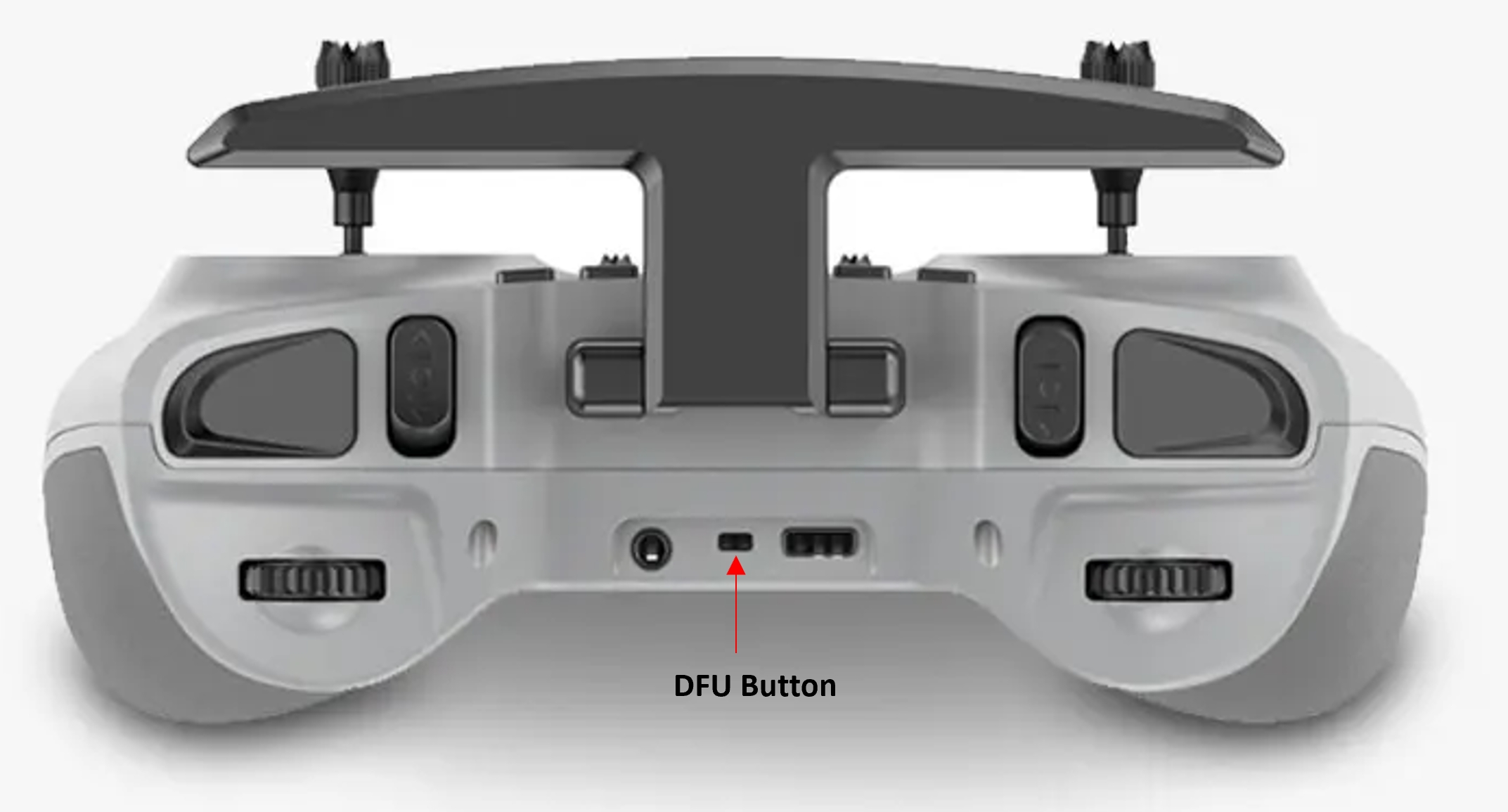
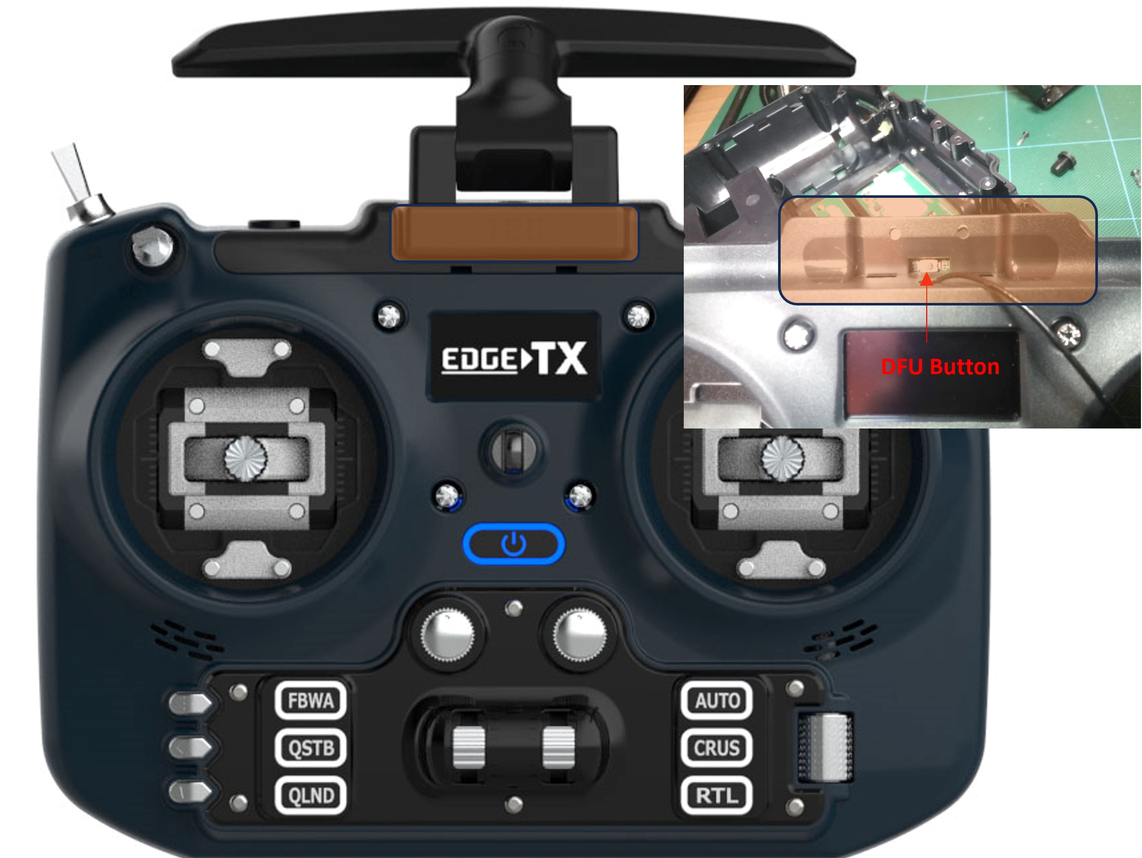
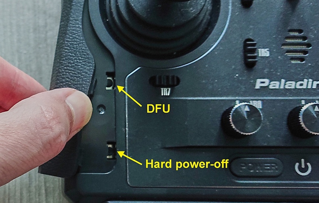
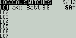
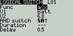
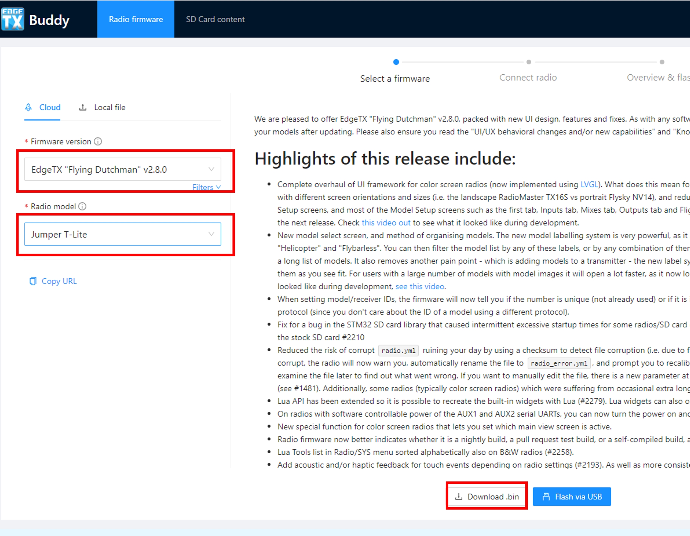
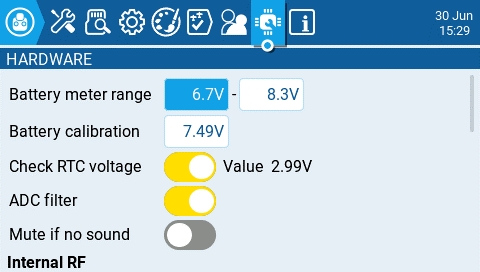
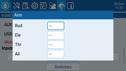
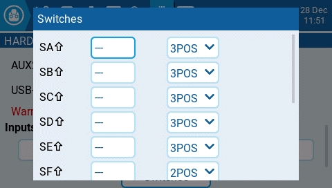
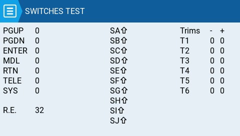
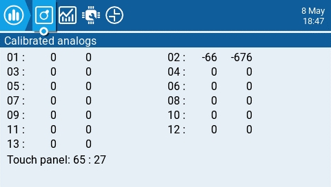
Below are descriptions and configuration options for widgets included with EdgeTX.
Displays a graphical representation of the charge level of a Lipo/Li-ion. It will automatically detect the cell count of the battery. It works with telemetry where only the total battery voltage is received. The configurable options are:
Sensor - Sensor for the battery voltage to use.
Color - Opens the color picker to choose the color for the text.
Show_Total_Voltage - Shows total battery voltage (instead of calculated cell voltage) when enabled.
Displays a graphical representation of the charge level of a Lipo/Li-ion. It works with telemetry where individual cell voltage is received, such as FLVSS liPo Voltage Sensor. The configurable options are:
Sensor - Sensor for the battery voltage to use.
Color - Opens the color picker to choose the color for the text.
Shadow - When enabled, adds a shadow to the text.
A counter that incrementally counts. The configurable options are:
Color - Opens the color picker to choose the color for the text.
Shadow - When enabled, adds a shadow to the text.
Demonstrates handling of key and touch events in full screen mode. For demo purposed only. The configurable options are:
Size - Changes the size of the box in full screen mode.
Counts your number of flights. It will give you a verbal queue when the flight has started, finished as well as the total flights for the model.
The configurable options are:
switch - Designated Arm/Safe switch.
motor_channel - Channel for the motor.
min_flight_duration - Minimum flight duration for the flight to be counted.
Additional notes regarding this widget:
The flight is considered successful if after 30sec the engine is above 25%, telemetry is active (to indicated that the model connected), and safe switch ON. The flight is considered ended after 8 seconds of battery disconnection (detected by no telemetry) -- warning: do NOT use this widget if model is using GV9 (GV9 FM0 is where the flight count is stored)!
The widget assumes the following: the model has a motor, the motor is activated on channel 3 (can be configured in settings), there is telemetry with one of the above [RSSI|RxBt|A1|A2|1RSS|2RSS|RQly], there is a safe switch (arm switch), and global variable GV9 is free (i.e. not used).
Shows a bar graph for the source value. The configurable options are:
Source - Source for the gauge.
Min - Minimum value for the gauge. This value will be 0%
Max - Maximum value for the gauge. This value will be 100%
A configurable analog style gauge with a needle. Also shows the minimum and maximum values that were read by the gauge with green and red needles. The configurable options are:
Source - Source for the gauge.
Min - The minimum (lowest) gauge value.
Max - The maximum (highest) gauge value.
HighasGreen
The Ghost widget will display RF receiver or video transmitter telemetry data based on the mode that is configured.
In normal mode, the widget provides RF Mode (RFMD), Frame Rate (FRATE), Link Quality (RQLY), and Transmit Power (TPWR)
In video mode, the widget provides Video Band (VBAN), Video Frequency (VFRQ), Video channel (VCHAN), and Video Power (VPWR)
This widget is a demo for the LibGUI library. This library is not normally run by itself. Instead, it provides interactive functions to other Lua scripts that use it. The widget must be run in full-screen mode to demo the library's functionality.
Displays the selected model name and picture (if configured in model settings). The configurable options are:
Color - Opens the color picker to choose the color for the name text.
Size - Size for the name text. Options are STD (Default), BOLD, XXS, XS, L, XL, XXL
Fill background? - Adds a solid background color to the widget when enabled
Shows the channel output values in a bar graph. The number of channels that are displayed is dependent on the size of the widget. The configurable options are:
First channel - selects the first channel to display in the widget.
Fill background - Adds a solid background color to the widget when enabled
BG Color - Opens the color picker to choose the color for the background.
A demo widget to show you how the power port can be used. It must be run in full screen mode.
The EdgeTX version of the SoarOTX tool. It is a package of sailplane models for EdgeTX transmitters. It provides Lua scripts for timing and scorekeeping, graphing of log data (e.g. altitude graphs), and model configuration.
For more information about the configuration and use of this widget please see .
A demo of this tool can be seen here:
Displays a user-customizable text field. The configurable options are:
Text - Text to display
Color - Opens the color picker to choose the color for the text.
Size - Size for the text. Options are STD (Default), BOLD, XXS, XS, L, XL, XXL
Displays the selected timer. No configurable options other than timer selection.
Displays the selected timer with the timer text scaled based on the select widget size and has the following configuration options:
TextColor - Opens the color picker to choose the color for the text.
Timer - Timer to display.
use_days - Shows days when the time value is over 24 hours when enabled.
Displays GPS Information in text format. There are no configurable options.
Displays a numeric value of the defined source as text. The configurable options are:
Source - source for the text to be displayed
Color - Opens the color picker to choose the color for the text. User can choose between RGB and HSV color model to choose the color. You can also select one of the configured theme system colors.
Shadow - When enabled, adds a shadow to the text.
Displays a numeric value of the defined telemetry source as text. The text will scale based on the size of the widget grid that is selected. The widget will detect the end of the flight (by no longer receiving telemtry) and will then display the min and max values of the configured telemetry sensor.
The configurable options are:
Source - Telemetry source for the text to be displayed
Color - Opens the color picker to choose the color for the text. User can choose between RGB and HSV color model to choose the color. You can also select one of the configured theme system colors.
PostFix - Appends a text label after the configured telemetry name label.
The Radio Setup screen is where you configure basic settings for your radio. It contains the following options:
Date - The current date. This date is used for the SD card log files.
Time - The current time. This time is used for the SD card log files.
Batt. range - Sets the maximum and minimum voltage for the battery meter. This should be set based on the type of battery you are using.
Mode - configures when to play sounds.
All - Beeps when the buttons are pressed and sounds are played when there are alerts or warnings.
No Key - No beeps when buttons are pressed or the scroll wheel is turned but does play sounds when there are alerts or warnings. Also plays sounds triggered by special functions.
Alarm - Only plays alarm or warning sounds. Also plays sounds triggered by special functions.
Volume - The master volume for the radio.
Beep Volume - Self-explanatory
Beep Length - Self-explanatory
Beep Pitch - Self-explanatory
Wav volume - The volume for alerts and warnings and sounds that are played with the Play track special function
Bg volume - The volume for background .wav files (music) that are played with the BGMusic special function
Startup sound - When enabled (default setting), plays the "Welcome to EdgeTX" sound on radio startup. The relevant file is located in /SOUNDS/??/SYSTEM/hello.wav (where `??` represents the two letter directory for your sound pack).
Volume - Volume for variometer beeps
Pitch zero - Low pitch frequency
Pitch max - High pitch frequency
Repeat Zero - The time before the tone repeats in milliseconds
Mode - configures when the radio vibrates.
All - Vibrates when the buttons are pressed and when there are alerts or warnings.
No Key - No vibrations when buttons are the pressed or scroll wheel is turned but does vibrate when there are alerts or warnings.
Alarm - Only vibrates for alarms or warning sounds.
Length - Duration of vibration.
Strength - Strength of vibration
Battery Low - Voltage to trigger low battery alarm.
Inactivity - Time to trigger inactivity warning.
Memory low - Enable/disable low memory warning.
Sound Off - An "alarms disabled" visual warning is displayed when the transmitter is turned on if the sound mode is set to quiet.
Mode
Off – Always off.
Keys – Turns on when buttons are pressed.
Ctrl – Turns on when sticks, switches, and knobs are used.
Both
Duration - The length in seconds that the backlight is on. The minimum value is 5 seconds. The maximum value is 600 seconds.
Brightness - Adjusts the screen backlight brightness level.
Contrast - For LCD displays, adjusts the screen contrast setting. For OLED displays. adjusts the OLED brightness level.
Alarm - The backlight turns on when there are alarms or warnings.
Splash Screen - Duration to display the splash screen. The options are --- (no splash screen), 2s, 3s, 4s, 6s, 8s, 10s, 15s
Power On delay - The delay between when the power button is pushed and when the radio turns on. The options are: 0s, 0.5s, 1s, 2s, 3s
Power Off delay - The delay between when the power button is pushed and when the radio shuts off. The options are: 0s, 0.5s, 1s, 2s, 3s, 4s. It is recommended to set at least a 1s delay in order to prevent the radio from being shut off in the case of an accidental button press.
Power Auto Off - If enabled (not enabled by default), if the handset is left inactive, with no trainer or telemetry link active, it will automatically turn off after the configured duration. You can select from 0 (disabled) up to 255 (minutes).
Power ON/OFF Haptic - If enabled (enabled by default), after the power on and power off delays have been served, there will be a haptic vibration to indicate the radio is powering on or off.
Owner ID (select transmitters) - Custom registration ID used only for users with ISRM internal RF modules, or on transmitters that support FrSky ACCESS external modules. If not configured manually, a random value will be used.
Time Zone - The time offset from UTC where the radio is being used. Can be configured in 15 minute increments.
Adjust RTC - Adjust the transmitter's real-time clock to match the time determined by the GPS.
GPS Coords - The GPS coordinate format that will be displayed.
Misc Settings
Country code - Used by some RF modules to ensure adherence to local regulatory RF requirements. Options are America, Japan, Europe.
Voice language - Language for the voice pack. This setting and the voice pack folder on the SD card must match for the sounds to be played.
Units - Units of measure. Options are metric or imperial.
PPM Units - Level of accuracy for PPM values are displayed. Options are 0.- , 0.0 or us (microseconds).
Play delay (switch middle position) - The minimum time in milliseconds a switch must be in the middle position before a special function will get activated. This is used to prevent the middle position from being activated on a three-position switch when switching from low position to high position.
USB Mode - Sets the default action when a USB cable is plugged into the USB data port and the radio is powered on. Options are: Ask (ask on connect, the default), Joyst (Joystick) , SDCard (Storage), and Serial.
Def Chan Ord - The default channel order for new models and the trainer screen. The letters stand for: A = Aileron, E = Elevator, T = Throttle, R = Rudder. Changing this setting does not affect existing models. On Surface Radios, the letters stand for S=Steering, T=Throttle.
RotEnc Mode (Rotary Encoder Mode) (select radios)- Sets the direction of the rotary encode for the Roller. The options are:
Normal (default)
Inverted = Reverses the direction of the roller
V-I H-N = Vertical Inverted, Horizontal Normal
V-I H-A
Mode - The stick mode that will be used for the transmitter. Defined by what actions the left stick takes. The options are:
The Enabled Features section of Radio Setup allows you to configure the Global settings for which tabs are visible in the Radio Setup and Model Settings area of EdgeTX. The configuration setting for the active model will show to the right of the checkbox. The model configuration will override the global configuration (which will be indicated by the "Off" and "On" shown next to any model level overrides).
Pressing the [PAGE>] button will take you to the Global Functions screen.
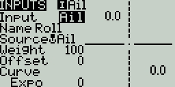

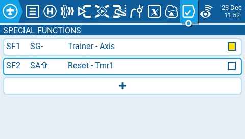
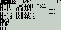
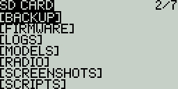
Lithium_Ion - Adjusts the minimum battery voltage used in calculating the remaining battery percentage from 3.0 to 2.8 when enabled.
debug - When enabled, shows status information on the widget.
Precision - The precision of the number value to display in decimals.
Use Theme Color - When enabled, overrides the text color with the text color of the configured theme.
Color - Opens the color picker to choose the color for the output bars.
Alignment - Alignment of the text in the text box. Options are: Left, Center, Right
Align Value - Aligns the value text. Options include: Left, Center, Right
RSSI Shutdown - Checks if a receiver is still connected to the radio on attempted shutdown. Makes an audio and visual alert if one is detected.
Trainer Shutdown - Checks if there is a trainer signal still active on attempted shutdown. Makes an audio and visual alert if one is detected.
ON – Always on.
V-N E-I = Vertical Normal, Edit Inverted (inverted when editing text)
Aileron (Roll)
Elevator (Pitch)
Rudder (Yaw)
Throttle
4: Left = Ail+Thr
Aileron (Roll)
Throttle
Rudder (Yaw)
Elevator (Pitch)
1: Left = Rud+Ele
Rudder (Yaw)
Elevator (Pitch)
Aileron (Roll)
Throttle
2: Left = Rud+Thr
Rudder (Yaw)
Throttle
Aileron (Roll)
Elevator (Pitch)


3: Left = Ail+Ele
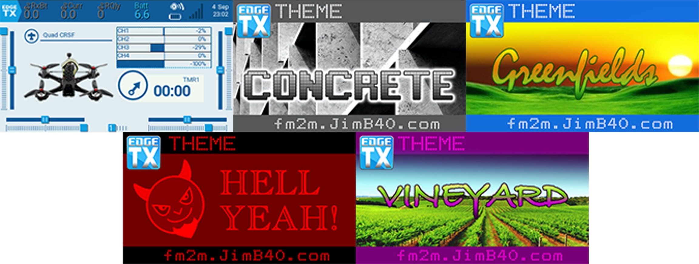
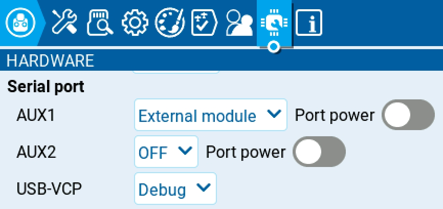
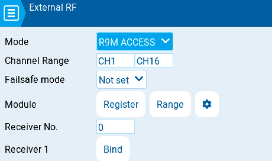
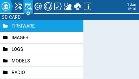
EdgeTX can output joystick / gamepad information via USB HID with ID (VID_1209&PID_4F54 / 1209:4F54).
EdgeTX performs configurable input processing including dead bands, mixing, and non-linear scaling.
A wide variety of run EdgeTX. By default all devices output the same "Classic Joystick" report format with 8 analog axis and 24 digital buttons.
Buttons are digital (0 = off, 1 = on).
Analog axis have 11 bit resoultion.
Linux's uses open (fcntl.h) with /dev/input/event[...] and read (unistd.h) to read input_event (linux/joystick.h).
EVIOCGID : device_id.vendor is 4617 / 0x1209
EVIOCGID : device_id.product is 20308 / 0x4F54
Linux's uses open (fcntl.h) with /dev/input/js and read (unistd.h) to read js_event (linux/joystick.h).
JSIOCGNAME is "EdgeTX [...] Joystick" or "OpenTX [...] Joystick". The middle part ("[...]") is device specific.
Windows's uses IDirectInputDevice8::GetDeviceState to read DIJOYSTATE (dinput.h). DIJOYSTATE2 (c_dfDIJoystick2) outputs the same information.
DIDEVICEINSTANCE.guidProduct starts with "4F541209-". The trailing part of the GUID is device specific.
Windows' uses joyGetPosEx to read JOYINFOEX (joystickapi.h). The older joyGetPos / JOYINFO only support CH1-CH3 and CH9-CH32 with the same mapping as the newer JOYINFOEX.
JOYCAPS.wMid is 4617 / 0x1209
JOYCAPS.wPid is 20308 / 0x4F54
Windows' uses GetRawInputData (WinUser.h), HidP_GetUsageValue and HidP_GetUsages (hidpi.h).
RID_DEVICE_INFO_HID.dwVendorId is 4617 / 0x1209
RID_DEVICE_INFO_HID.dwProductId is 20308 / 0x4F54
Windows' uses winrt::Windows::Gaming::Input::RawGameController (winrt/Windows.Gaming.Input.h).
RawGameController::HardwareVendorId is 4617 / 0x1209
RawGameController::HardwareProductId is 20308 / 0x4F54
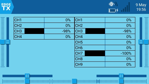
CH5
ABS_RY
EV_ABS 4
CH6
ABS_RZ
EV_ABS 5
CH7
ABS_THROTTLE
EV_ABS 6
CH8
ABS_RUDDER
EV_ABS 7
CH9
BTN_SOUTH
EV_KEY 304 / 0x130
CH10
BTN_EAST
EV_KEY 305 / 0x131
CH11
BTN_C
EV_KEY 306 / 0x132
CH12
BTN_NORTH
EV_KEY 307 / 0x133
CH13
BTN_WEST
EV_KEY 308 / 0x134
CH14
BTN_Z
EV_KEY 309 / 0x135
CH15
BTN_TL
EV_KEY 310 / 0x136
CH16
BTN_TR
EV_KEY 311 / 0x137
CH17
BTN_TL2
EV_KEY 312 / 0x138
CH18
BTN_TR2
EV_KEY 313 / 0x139
CH19
BTN_SELECT
EV_KEY 314 / 0x13A
CH20
BTN_START
EV_KEY 315 / 0x13B
CH21
BTN_MODE
EV_KEY 316 / 0x13C
CH22
BTN_THUMBL
EV_KEY 317 / 0x13D
CH23
BTN_THUMBR
EV_KEY 318 / 0x13E
CH24
(no name)
EV_KEY 319 / 0x13F
CH25
BTN_TRIGGER_HAPPY1
EV_KEY 704 / 0x2C0
CH26
BTN_TRIGGER_HAPPY2
EV_KEY 705 / 0x2C1
CH27
BTN_TRIGGER_HAPPY3
EV_KEY 706 / 0x2C2
CH28
BTN_TRIGGER_HAPPY4
EV_KEY 707 / 0x2C3
CH29
BTN_TRIGGER_HAPPY5
EV_KEY 708 / 0x2C4
CH30
BTN_TRIGGER_HAPPY6
EV_KEY 709 / 0x2C5
CH31
BTN_TRIGGER_HAPPY7
EV_KEY 710 / 0x2C6
CH32
BTN_TRIGGER_HAPPY8
EV_KEY 711 / 0x2C7
[...]
[...]
CH32
JS_EVENT_BUTTON 23
CH7
rglSlider[1]
CH8
rglSlider[0]
CH9
rgbButtons[0]
CH10
rgbButtons[1]
[...]
[...]
CH32
rgbButtons[23]
CH7
dwUpos
CH8
(not available)
CH9
dwButtons & 0x000001
CH10
dwButtons & 0x000002
CH11
dwButtons & 0x000004
[...]
[...]
CH32
dwButtons & 0x800000
CH4
HidP_GetValueCaps [4]
0x01
0x33
CH5
HidP_GetValueCaps [3]
0x01
0x34
CH6
HidP_GetValueCaps [2]
0x01
0x35
CH7
HidP_GetValueCaps [1]
0x01
0x36
CH8
HidP_GetValueCaps [0]
0x01
0x37
CH9
HidP_GetButtonCaps [0]
0x09
0x01
CH10
HidP_GetButtonCaps [0]
0x09
0x02
[...]
[...]
[...]
[...]
CH32
HidP_GetButtonCaps [0]
0x09
0x18
[...]
[...]
CH32
buttonArray[23]
CH1
ABS_X
EV_ABS 0
CH2
ABS_Y
EV_ABS 1
CH3
ABS_Z
EV_ABS 2
CH4
ABS_RX
EV_ABS 3
CH1
JS_EVENT_AXIS 0
CH2
JS_EVENT_AXIS 1
[...]
[...]
CH8
JS_EVENT_AXIS 7
CH9
JS_EVENT_BUTTON 0
CH10
JS_EVENT_BUTTON 1
CH1
lX
CH2
lY
CH3
lZ
CH4
lRx
CH5
lRy
CH6
lRz
CH1
dwXpos
CH2
dwYpos
CH3
dwZpos
CH4
dwVpos
CH5
(not available)
CH6
dwRpos
CH1
HidP_GetValueCaps [7]
0x01
0x30
CH2
HidP_GetValueCaps [6]
0x01
0x31
CH3
HidP_GetValueCaps [5]
0x01
CH1
axisArray[0]
CH2
axisArray[1]
[...]
[...]
CH8
axisArray[7]
CH9
buttonArray[0]
CH10
buttonArray[1]
0x32
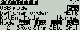
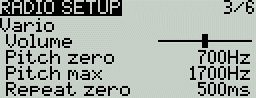
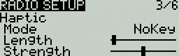
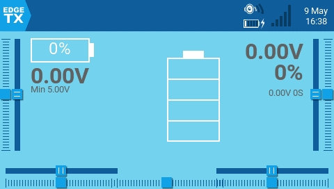
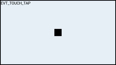
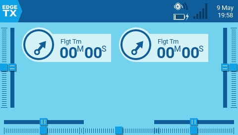
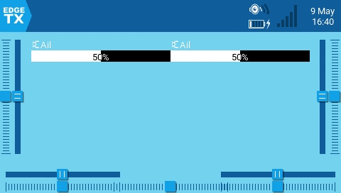
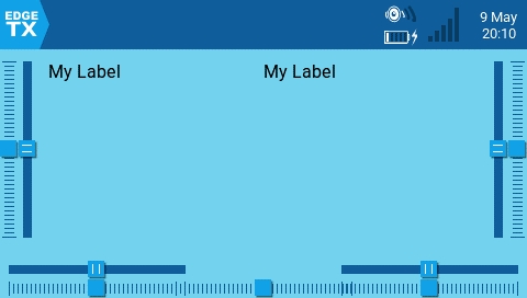
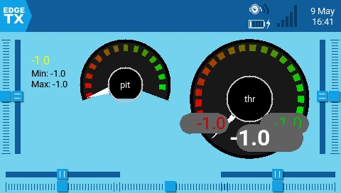
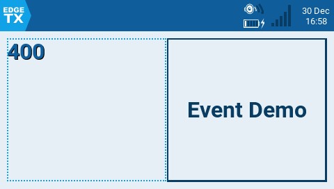
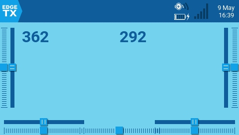
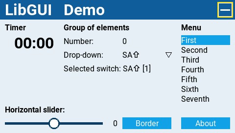
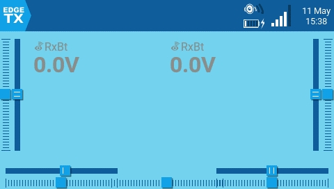
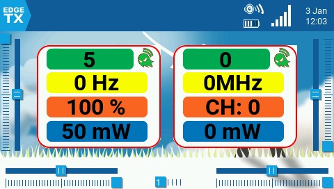
The Setup screen is where you start to configure your model. It contains the following settings:
Name - Name of the model. The maximum number of characters is 10.
To edit the text, using the [roller] or [dial], press the button, scroll to select the desired letter, then press the button again to move to the next space. To toggle between lower and upper case, long-press the button. Press the [RTN] button to exit out of text editing mode.
Image - Image displayed on the main view (only for radios with 212 x 64 displays).
Timer 1/2/3 - There are 3 configurable timers in EdgeTX. The following configuration options will be displayed once the timer is no longer set to OFF:
[Mode] - The options include:
OFF - The timer is not used
ON - The timer runs all the time
Strt (Start) - The timer starts once the configured switch is activated. After the time is started, the timer ignores the switch position.
[Switch] - Select the switch that will trigger the timer to start. If no switch is selected, the timer will trigger based only on the configured mode. In addition to a switch, you can also select a trim, a telemetry source (triggered when telemetry data is received from that source), or physical activity (stick movement or button press) (labeled as ACT)
Name - Name of the timer
Start - The time used for the timer's advanced functions. The default value is 00:00 and when left as such, the timer operates like a stopwatch, counting upward until stopped. If a different time is entered in this box, then the additional field will appear next to the time with the options: Remain or Elaps.
If set to Remain, the counter will function like a countdown timer - counting down from the designated time to zero and then alerting the user. If set to Elaps, the timer functions like an alarm, counting up from zero until the designated time and then alerting the user.
Persist. (Persistence):
OFF - The timer value is reset when switching models or when the radio is turned off / on.
Flight - The timer value is NOT reset when switching models or when the radio is turned off / on. The timer value is only reset when the Reset flight option is selected in the menu.
Manual Reset - The timer value is reset only when it is individually selected to be reset (example: Reset timer1) in the menu.
Minute (Minute Call) - If selected, you will be notified every minute that passes as described in the Countdown option.
Count Down:
Silent - No notification is given until the timer reaches zero. When it reaches zero, you will hear one beep.
Beeps - The radio will beep every second starting at the time designated.
Voice - The radio will count down by second starting at the time designated.
The customizable switches are a type of multi-position switch (on select transmitters) that are managed directly by EdgeTX. Physically, they look like a regular 6-pos switch but are much more flexible.
Unlike other switches managed at the radio level, customizable switches are defined per model and configured in the model setup page. They contain the following configuration options:
Switch Type
None: the switch is disabled
Toggle: they are active only during the push duration
2POS: pushing the switch will alternate the state between OFF and On
Switch group
A traditional 6POS is a group of 6 switches that work together, where only one can be active at a time. Customizable switches expand that concept and let you choose how the switches should be grouped.
'-' defines a customizable switch with no group. Pushing it will only affect this switch.
'1', '2' or '3' define groups. All the switches in a group act together, where only one (the last pushed) can be active.
Always on groups
Selecting this check box makes the assigned group act a bit like a traditional 6-position switch where one button (and only one) from the group must be on at all times.
Startup Position
Start - Defines the state that each switch will be in when the model is loaded.
↑ Switch is inactive
↓ Switch is active
= Switch is set to the same state it was in when the model was last used (it keeps old state).
E.Limits (Extended Limits) - When enabled, it increases the minimum and maximum range for the output values to -150 and 150. Extended limits are necessary if the full range of the control surface cannot be reached with standard limits.
E. Trims) Extended Trims - Increases the maximum trim adjustment value from ±25% to ±100%.
Reset - This resets all trim values to zero.
Show trims - When set to Yes, it will display the numerical trim value on the trim bar. When set to CHANGE, it will display the numerical value once the trim is no longer at zero.
Trim Step: - Defines the amount of increase/decrease in trim when the trim switch is pressed.
Course = 1.6%
Medium = 0.8%
Fine = 0.4%
Extra Fine = 0.2%
The throttle related configuration options below are displayed in collapsible menu.
T-Reverse - When enabled, this option reverses the output direction of the configured throttle channel.
T-Source - The source that will be used for the throttle.
T-Trim-Idle - When enabled, the throttle trim will only affect the bottom portion of the throttle band.
T-Trim-SW - The trim switch that will be used to trim the throttle. It is possible to substitute the throttle trim switch with the aileron, rudder, or elevator trim switches.
Whenever a new model is loaded, EdgeTX will conduct pre-flight checks based on the checks that are configured on this page. If any of the checks are failed, EdgeTX will give the user an audio and visual warning that must be acknowledged before using the model. The following preflight checks below are displayed in collapsible menu.
Checklist - When this option is selected, the model notes file will be displayed when the model is loaded. A valid model notes file must be in the Models folder on the SD card. The model notes file must be a .txt file and must have the EXACT same name as the model it is for, for example: Mobula6.txt. The text in the file is up to the user.
C-Interact (Interactive checklist) - This option is used with the Checklist option. When this option is selected, any line of text in the checklist file that begins with = will display as a check box when the checklist is displayed. All displayed checkboxes must be checked by selecting them in order to close the checklist.
T-Warning - When selected, the radio will check that the throttle is at the minimum value for the configured throttle source in the T-Source configuration option.
Cust-Pos - When this option is selected, the value designated in Pos. % will be used for the T.Warning.
Pos. % - minimum value of the throttle for the throttle warning when Cust-Pos is enabled.
S-Warning - The section displays all the switches that are configured on the radio and allows you to select which position is the correct position for the switch state check. Selecting the switch will cycle through the available switch positions or turn the check off for the switch completely. A long press of [Enter] while this section is highlighted will set all the switch positions to the currently configured physical positions of the switches.
Pot warn. - When activated, this option checks the position of the pots & sliders. There are three options - OFF, ON and Auto. When ON or AUTO is selected, buttons for the available pots and sliders will appear. To enable the pot warning for an individual pot, select the pot with the [roller] or [dial] and click the button to highlight it. Highlighted pots are enabled.
OFF - Pot and slider positions are not checked.
ON- Positions are checked against manually configured pot and slider positions. To manually set the check position, select the item that you want to set, and long-press the [Enter] button to set its current position for the check.
Auto - Positions are checked for pots and sliders and compared to the last automatically saved position before the radio was turned off or the model was changed.
Ctr Beep - Allows you to turn on/off the center beep function for the individual sticks, pots, and sliders by highlighting them with the [roller] or [dial] and pressing the button. When a switch is highlighted, the function is enabled.
Glob. Funcs - When enabled, global functions programmed in the radio settings will apply to this model. When disabled, global functions will not apply to this model.
ADC filter - Enables/disables the ADC filter for this model. The Global option will take the value designated in the radio settings, which is on by default.
The configuration settings for both the Internal and External RF sections work the same. The only difference is that the Internal RF section is for configuring the built-in module and the External RF section is for configuring an RF module in the external module bay.
The configuration options are: OFF or the module name of the installed module as configured in the radio settings. Configuration options are unique to each installed module. Please consult the manufacturer's documentation for configuration options.
Receiver number - A receiver number is a user-assigned number for a model that is sent to the receiver when bound. Each model must have a unique receiver number. However, models using different protocols may have the same receiver number without issues. EdgeTX will inform you when a receiver number is unique or if it is already being used with a text above the number field.
Trainer Mode - The Trainer Mode option is where you can configure the CPPM passthrough mode and method. When enabled, this allows the CPPM signals from a radio in Slave mode to be passed through to another radio in Master mode which will then pass the signal to the model it is connected to. CPPM passthrough can be used for several different use cases, such as: connecting a head tracker, Instructor / Student training mode, and controlling complex models that require more stick inputs than available on a standard transmitter.
Master mode - This is the mode for the radio that will be connected to the model. This radio also shall configure the special/global function (Trainer) to activate the passthrough mode. When the passthrough mode is activated, the CPPM signals from the radio in Slave mode will be sent to the model for control.
Slave mode - This is the mode for the radio that will pass it's CPPM values to the radio in Master mode, which are then sent to the model.
Below are the possibile configuration options:
OFF - Trainer mode is not used for this model.
Master/Jack - Master mode using a cable connection.
Slave/Jack - Slave mode using a cable connection.
Ch. Range - This is the range of channels that will be sent to the radio in Master mode. Channel 10 is the recommended last channel to use.
The Enabled Features section allows you to configure which pages are visible in the selected model's radio setup and model settings area of EdgeTX. The page names are displayed in a collapsible menu with the following configurable options:
Global - When selected, the tab will take the global value configured in the Enabled Features area in Radio Setup. The configured global value will display next to the option.
On - When selected, this tab will be visible when this model is loaded.
Off - When selected, this tab will not be visible when this model is loaded.
The USB Joystick has two possible modes, Classic and Advanced.
In Classic mode, the radio's configured output channels will be sent to the target device in numerical order and mapped to the device's preconfigured USB controller axes and buttons. Below is the default channel mapping for Microsoft Windows.
Ch 1 - X Axis
Ch 2 - Y Axis
Ch 3 - Z Axis
Ch 4 - X Rotation
In Advanced mode you can configure the following additional options:
If. mode (Interface mode): This indicates to the target device (the device you are connecting your transmitter to) what type of device you are connecting. The options are Joystick, Gamepad, MultiAxis.
Circ. cut (Circular cutout) - For axis pairs (X-Y, Z-rX): By default, the range of the axis pairs is a rectangular area. With this option, the axis will be limited to a circular area (like gamepad controllers commonly are). Options are : None or X-Y, Z-rX or X-Y, rX-rY or X-Y, Z-rZ
Channel Settings
Mode - For each output channel, you can select the mode that you want to use for that channel. The available options are None, Btn, Axis, Sim.
None - Channel is not used
Btn - Channel is used to simulate a button. Configuration options include:
Inversion - Inverts the output channel signal. Options are: On / Off
Button Mode -
Axis - The channel is used to simulate an axis and will be mapped to one of the target device's default axes.
Axis options are: X, Y, Z, rotX (rotation X), rotY, rotZ
Sim - The channel is used to simulate a common sim axis and it will be listed on the target device as the selected option (ex: Thr)
Sim Axis options are: Ail, Ele, Rud, Thr, Acc, Brk, Steer, Dpad
Pressing the [PAGE>] button will take you to the Heli Setup screen.
TH% (Throttle %) - The timer counts proportionally to the throttle. It counts in real-time at full throttle and half speed at 50% throttle.
THt (Throttle Start) - The timer starts once the throttle is raised and the configured switch is activated. After starting, the timer ignores the throttle position and will keep counting unless the switch is deactivated.
Exponential = 0.2% near the center and the step value increases exponentially as the distance from the center increases.
PPM frame - The first field is the length of the PPM frame. The second field is the stop length/delay between pulses. The dropdown is to select the polarity of the signal. The frame length is automatically adjusted to the correct value when the number of transmitted channels is changed. However, this automatically assigned value can be manual changed. Note: In most cases, the default setting does not need to be changed.
Master / Bluetooth - Master mode using a Bluetooth connection (if installed in radio).
Slave / Bluetooth - Slave mode using a Bluetooth connection (if installed in radio).
Master / Multi - Master mode using an additional externally mounted Multi-protocol module for the connection. For more information on this setup, see Set-up wireless trainer with a Multi -protocol module
Ch 5 - Y Rotation
Ch 6 - Z Rotation
Ch 7 - Dial
Ch 8 - Slider
CH 9 - Ch 32 - Buttons 1 - 24
Normal - Each postion of a multiposition switch is represented by a button. The current switch state is represented by a continous button press.
Pulse - Similar to "Normal" mode. However, instead of continous button press it is represented by a short button press.
SWEmu - The toggle switch emulations a push button. The first press turns the virtual button on, the second press turns it off.
Delta - The change of the output channel is represented by 2 buttons. While the output value is decreasing, the first button is pressed. When the output value is increasing, the second button is pressed. If there is no change, then no buttons will be pressed.
Companion - This option should be selected when using your transmitter to control the simulator in EdgeTX Companion. It allows the multi-position switches to function properly in the simulator.
Positions - The type of button that will be simulated.
Push - will only map to one button
2POS - 8 POS - will map to the number of buttons that the switch has (ex: 3POS will map to 3 buttons).
Button No: The button number that the output will be mapped to and sent to the target device as.


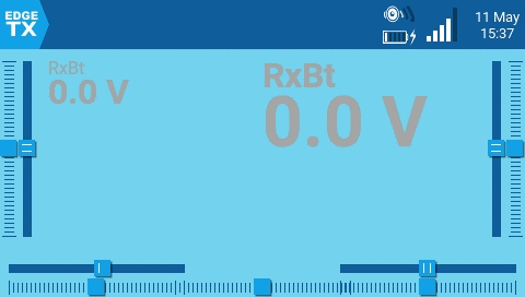
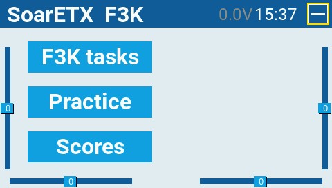
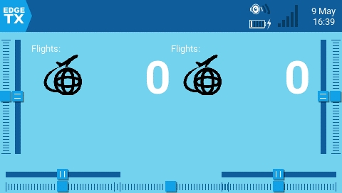
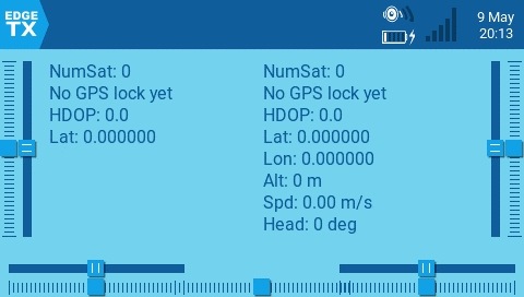
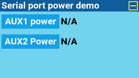
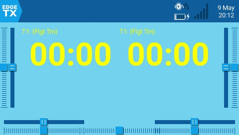
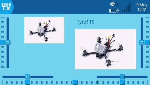
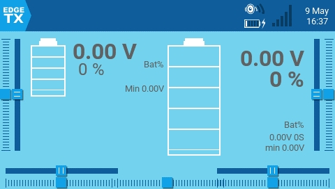
Please try the classic mode first. Handling joystick input has undergone many different designs. For example Windows has 6 joystick APIs - all with different quirks.
Interface mode Gamepad is usually the right one.
To ease switching between Advanced and Classic mode try using channels 1 - 8 for axis and channels 9 - 32 for buttons.
After changing the joystick configuration you likely have to disconnect and then reconnect the USB cable. Otherwise systems might still use the old joystick description to read the new data.
Most modern applications use the USB HID ID to identify the meaning of an axis.
Legacy applications frequently use the order the axis where configured in.
A few applications use the reverse order the axis where configured in.
Duplicate axis are rarely supported. Some APIs do support two Slider axis.
Similar layouts:
Sim Dpad emulates a directional pad also known as hat switch or point of view switch. Most application decode the 8 ordinal directions and "center". Some applications only decode the 4 cardinal directions and "center" (e.g. Northeast is treated as North).
Buttons are identified by their USB HID ID.
The meaning of a specific button ID is not standardized.
Duplicate buttons (e.g. button 1, button 1) are not supported. The button with the higher channel number is used.
Buttons as axis: Some applications need analog button information. Use a mixer to forward the digital button state to an analog axis.
Inverted axis: Many applications expect the left and right Y axis to go the other way. The direction can be reversed with Weight -100% or in the advanced Joystick configuration.
Windows does support "axis" and "sim". However mixing both types is not always supported.
Linux maps following inputs onto the same axis and uses the input value with the lowest channel number.
sim Thr + axis Slider → ABS_THROTTLE
sim Rud + axis Dial → ABS_RUDDER
axis Wheel + sim Steer → ABS_WHEEL
Android treats sim Acc and sim Brk as half axis. EdgeTX channel outputs [-100%, 0% and +100%] are interpreted by Android as [0%, 50% and 100%]. Consider following configuration if your physical input is one analog stick:
sim Acc = input (axis 1: Offset -50%, Func "x>0") mixed with (Weight 200%)
sim Brk = input (axis 1: Offset -50%, Func "x<0") mixed with (Weight -200%)
axis Y
axis Y
CH3
axis Z
axis Z
axis Z
axis Z
axis Z
CH4
axis rotZ
axis rotX
axis rotZ
axis rotX
axis rotX
CH5
sim Brk
axis rotZ
axis rotX
axis rotY
axis rotY
CH6
sim Acc
axis rotY
axis rotY
axis rotZ
axis rotZ
CH7
axis Slider
axis Slider
axis Slider
CH8
sim Dpad
axis Dial
sim Dpad
axis Dial
axis Slider
South
-52.8%
-41.2%
Southwest
-41.1%
-29.5%
West
-29.4%
-17.8%
Northwest
-17.7%
-6.1%
Center
-6.0%
5.7%
North
5.8%
17.4%
Northeast
17.5%
29.1%
East
29.2%
40.8%
Southeast
40.9%
52.5%
South
52.6%
64.3%
Southwest
64.4%
76.0%
West
76.1%
87.7%
Northwest
87.8%
100.0%
axis rotY
Ry
0x00010034
axis rotZ
Rz
0x00010035
axis Slider
Slider
0x00010036
axis Dial
Dial
0x00010037
axis Wheel
Wheel
0x00010038
sim Ail
Aileron
0x000200B0
sim Ele
Elevator
0x000200B8
sim Rud
Rudder
0x000200BA
sim Thr
Throttle
0x000200BB
sim Acc
Accelerator
0x000200C4
sim Brk
Brake
0x000200C5
sim Steer
Steering
0x000200C8
sim Dpad
Hat switch
0x00010039
Ghost buttons: For Joysticks and Gamepads the required minimum amount of buttons is automatically created. Similarly if only button 15 is configured the missing buttons 0 - 14 are automatically created. These buttons have no input and are always off.
Android generally supports buttons 0 to 14 with the same mapping as Linux. Support for buttons in bold is mandatory for all Android devices.
Widows generally supports buttons 0 to 9 with the same mapping as Xbox.
circle
X
0x00090003
button 3
BTN_X - 307
triangle
Y
0x00090004
button 4
BTN_Y - 308
L1
left bumper
0x00090005
button 5
BTN_Z - 309
R1
right bumper
0x00090006
button 6
BTN_TL - 310
L2
back
0x00090007
button 7
BTN_TR - 311
R2
start
0x00090008
button 8
BTN_TL2 - 312
create
left stick
0x00090009
button 9
BTN_TR2 - 313
options
right stick
0x0009000A
button 10
BTN_SELECT - 314
L3
left trigger
0x0009000B
button 11
BTN_START - 315
R3
right trigger
0x0009000C
button 12
BTN_MODE - 316
home
guide
0x0009000D
button 13
BTN_THUMBL - 317
touchpad
0x0009000E
button 14
BTN_THUMBR - 318
mute
0x0009000F
button 15
0x00090010
button 16
BTN_TRIGGER_HAPPY1 - 704
0x00090011
button 17
BTN_TRIGGER_HAPPY2 - 705
0x00090012
button 18
BTN_TRIGGER_HAPPY3 - 706
0x00090013
button 19
BTN_TRIGGER_HAPPY4 - 708
0x00090014
button 20
BTN_TRIGGER_HAPPY5 - 709
0x00090015
button 21
BTN_TRIGGER_HAPPY6 - 710
0x00090016
button 22
BTN_TRIGGER_HAPPY7 - 711
0x00090017
button 23
BTN_TRIGGER_HAPPY8 - 712
0x00090018
button 24
BTN_TRIGGER_HAPPY9 - 713
0x00090019
button 25
BTN_TRIGGER_HAPPY10 - 714
0x0009001A
button 26
BTN_TRIGGER_HAPPY11 - 715
0x0009001B
button 27
BTN_TRIGGER_HAPPY12 - 716
0x0009001C
button 28
BTN_TRIGGER_HAPPY13 - 717
0x0009001D
button 29
BTN_TRIGGER_HAPPY14 - 718
0x0009001E
button 30
BTN_TRIGGER_HAPPY15 - 719
0x0009001F
button 31
BTN_TRIGGER_HAPPY16 - 720
0x00090020
CH1
axis X
axis X
axis X
axis X
axis X
CH2
axis Y
axis Y
OpenTX
EdgeTX pre 2.9
Orqa FPV.Ctrl
EdgeTX pre 2.9
Stadia
Android
XBox
Android
North
-100.0%
-88.1%
Northeast
-88.0%
-76.4%
East
-76.3%
-64.6%
Southeast
-64.6%
-52.9%
axis X
X
0x00010030
axis Y
Y
0x00010031
axis Z
Z
0x00010032
axis rotX
Rx
0x00010033
EdgeTX
Android / Linux
Dualsense
Windows / XBox
USB HID ID
button 0
BTN_A - 304
square
A
0x00090001
button 1
BTN_B - 305
cross
B
0x00090002
button 2
axis Y
BTN_C - 305
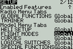
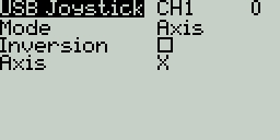
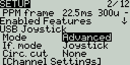
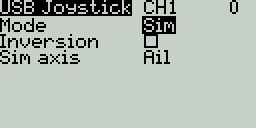
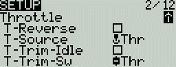
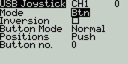
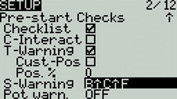
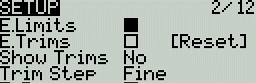